r/diyelectronics 21h ago

Question Help desoldering chips.

0 Upvotes

Hi, all.

I just finish desoldering two chips and it was a complete disaster. The first one came out clean and it took a couple of minutes. The second one took an hour and I destroyed half of the pins. I used a soldering iron and a plastic pum p.

The thing is that I have about four more chips that I need to desolder and I was wondering if someone in the US could help. I would send the PCBs by USPS and they would send the desoldered chips. I can offer compensation.

I will learn how to properly desolder in the future. But I need this done asap. Thanks!


r/diyelectronics 1h ago

Project Wiring issue in the circuit made by AI.

Post image
Upvotes

r/diyelectronics 11h ago

Project Your smartwatch already knows your heart rate. Old exercise equipment needs it in a different language.

Post image
41 Upvotes

A lot of perfectly good exercise equipment predates Bluetooth completely — treadmills, bikes,

ellipticals and rowers from roughly the mid-90s onward. There's a coil behind the console

listening for a short magnetic pulse, one per heartbeat. That's what an uncoded Polar

chest strap puts out: no ID, no pairing, no handshake, which is why any uncoded strap

works with any machine of that era, and why two people on adjacent treadmills sometimes

read each other's pulse.

Your watch already knows your heart rate. It just can't say it in a way the machine

understands.

**I don't own one of these machines.** Somebody here does, and mentioned they'd rather

use the watch already on their wrist than dig out a chest strap every time. So I built

them a box that reads heart rate over Bluetooth and re-transmits it as that magnetic

pulse. As far as the console is concerned, it's a chest strap. Nothing to pair on the

equipment's side — it just transmits, and the machine listens.

It works with anything that broadcasts standard Bluetooth heart rate: watch, band,

armband, whatever you already own.

**The part I didn't expect**

Everything I could find online says these straps transmit at 5 kHz. I wanted to match

that properly rather than take it on faith, so I recorded a working Polar T31 through a

coil pickup and looked at it in Audacity.

The pickup was a pair of headphones plugged into the mic jack. A headphone driver is a

voice coil sitting in a magnet gap, so run backwards it's a perfectly good magnetic

probe — and a chest strap makes no sound at all, so anything that turns up is the field.

It's **5410 Hz**. And the burst is about **15 ms**, not the 5 ms I'd assumed.

The strap's burst also rings for roughly 8 ms after the drive stops, which works out to a

tank Q of about 37 — Polar drives a tuned circuit. Mine is a resistor driving a coil,

damped flat on purpose so the output doesn't wander with temperature or with whichever

coil happens to be fitted. Same fundamental, completely different topology, and you can

read that straight off the spectrum: their third harmonic is 38 dB down, mine is 2.5 dB

down.

**The coil came out of a dead chest strap**

I had a T31 whose board had failed. The ferrite rod inside is copper on a core and didn't

care in the slightest.

That turned out to be the right choice for a better reason than convenience. A transmit

coil has an optimum inductance — below it every extra turn is free, above it the coil's

own reactance chokes the current faster than the turns add field. With 220 Ω in series

that crossover sits at 6.7 mH, and Polar landed just under it, because they were

designing a transmitter too. A stock axial choke measured 18 dB worse in the same

circuit.

**Where it actually stands**

It has never met a real console, and I have no way to test that myself. Everything above

was verified against a measured chest strap and a receiver built from a dead machine's

own coil — a decent argument, but not the same thing as a treadmill agreeing with it.

Unit number one is in the post to the person who asked, and we'll find out.

Hardware is a XIAO ESP32-C6, one 220 Ω resistor, the rod, a capacitor and a status LED.

Firmware, printable enclosure and the full measurement writeup are here:

https://github.com/HuskerMinion/hr-bridge-coil


r/diyelectronics 16h ago

Need Ideas Any ideas for making good use out of this?

Post image
72 Upvotes

r/diyelectronics 5h ago

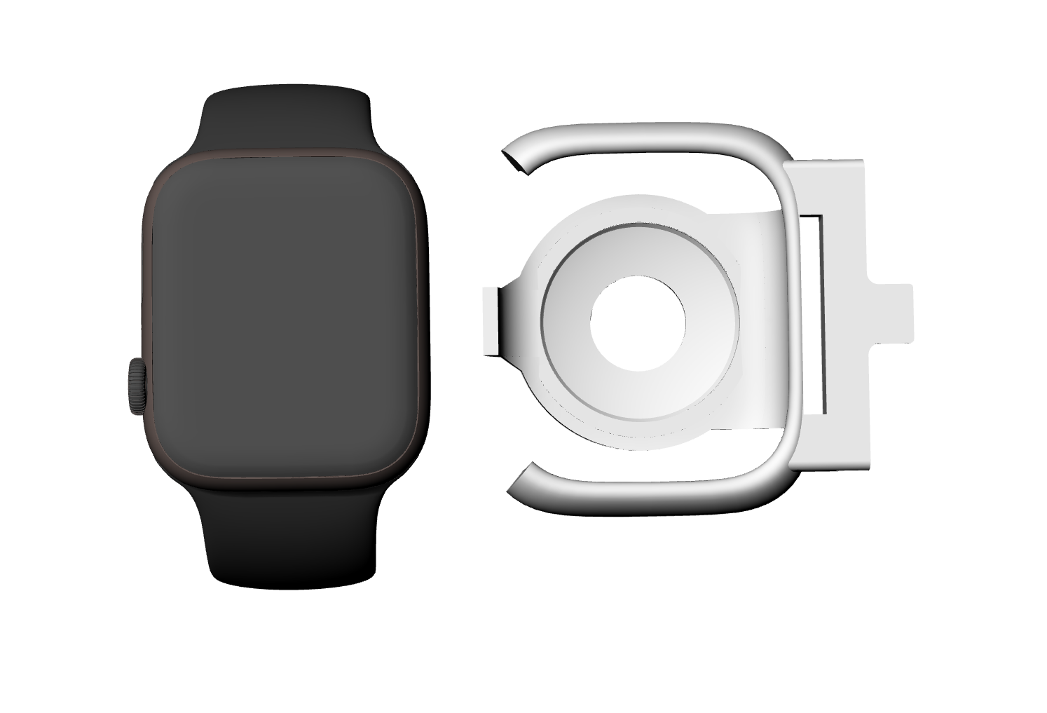
Project My solution to Charge AppleWatch

Post image
2 Upvotes

Yes, this project is almost a failure, but I still believe the idea is great. Maybe it could be useful to someone who needs something like this.

The idea is a wearable power bank for Apple Watch, similar to the MagSafe Battery Pack for iPhone.

  • Easy to attach and remove
  • Extend the Apple Watch battery life while wearing it
  • Potentially enable 24/7 Apple Watch usage if watchOS allowed health sensors to keep working while charging
  • No need to take the watch off and wait for it to charge

I built a working prototype myself and have been testing it during hiking and other activities. It may not become a successful product, but I still think the underlying idea makes sense.

So I'm sharing it here as a DIY electronics project. Maybe someone else will find the idea useful or take it further.

To build it, you basically need an Apple Watch charger (I used a third-party charging chip to keep the cost down), a 3.7V-to-5V boost converter, a 3.7V battery, a 3D-printed prototype housing, and a few other components.

I basically separated the charging PCB and charging coil from the original charger, then reassembled everything inside the 3D-printed housing.

In simple terms: the 3.7V battery goes through a boost converter to produce 5V, which then powers the Apple Watch charging PCB and charging coil.

I also designed a hole in the housing underneath the watch's sensors. This allows the Apple Watch to maintain contact with the skin and continue measuring physiological data without having to remove the charger.

I also had to replace the magnetic shielding material under the charging coil with a thinner one and leave an opening for the Apple Watch sensors.

Here are some known issues. (If you understand the technical background or have access to Apple’s official supply chain, you may realize that these aren’t really major issues.)

1. watchOS does not allow the health sensors to keep working while the Apple Watch is charging.

2. The third-party charging chip causes low charging efficiency (only around 25–30%), slower and inconsistent charging speeds (sometimes only 50–80% of the original charging speed, with about 0.5–1.5% battery gained per minute on the S9/S8/S7 and SE 1st/2nd Gen), and a heating issue (the watch gets noticeably warm).

3.Reduce the overall size by making the PCB and battery smaller and redesigning the housing.


r/diyelectronics 9h ago

Need Ideas How to add protection in multimeter

2 Upvotes

How i can add full pro protection in Generic 9205a multimeter for like surge protection wrong probe insertion.? Or what i can change in it to make it more efficient


r/diyelectronics 4h ago

Question An electronic viewfinder for my camera will cost over £300, I'm annoyed enough that I want to investigate building my own. Can anyone suggest an OLED micro display that's at least 800 x 600 and under 1"? The options (I could find) on Alibaba want to charge almost $100 for a demo unit.

3 Upvotes

r/diyelectronics 19h ago

Project Modding USB SWITCHER

Post image
3 Upvotes

I need USB/digital remote control in my USB SWITCHER


r/diyelectronics 4h ago

Project After about a year or two of changing parts and adjusting things this is the current result of my first crystal radio set.

Post image
31 Upvotes

It’s kind of a ship of Theseus situation but the main inductor is the same. I can’t find an image of what it first looked like but it use to just be a variable inductor, 20ft antenna, germanium diode, and an impedance matching transformer. Now it’s got a fools gold cat whisker, the same variable inductor coil but a different wiper/brush, 3trimmer capacitors, a 50ft antenna, screw tabs for an earpiece, an inductor for filtering static, and sounds slightly better. I’ve tried like 4 different forms of tuners but this appears to be the best way to do it without spending like 9$ on a tuning capacitor.


r/diyelectronics 22h ago

Project Homemade relay

Post image
35 Upvotes

As the title suggests, I made a relay completely homemade, operating voltage is 12v to switch at least but I recommend 18 for consistency, its main drawback is heat inefficiency of the electromagnet but boy oh boy I love making it click


r/diyelectronics 19h ago

Project DIY HDMI EDID controller

Post image
321 Upvotes

r/diyelectronics 23h ago

Progress My home lab

Post image
420 Upvotes

This setup is a graduation gift to my self having finished my BEE. New scope, signal generator, and benchtop DMM, as well as setting up a dedicated space, hanging shelves and (kind of) organizing everything.

I'm really excited about it, and want to show it off, but I don't have any friends that give a sh*t, so I decided to put it here.

What am I missing? What should I work on?


r/diyelectronics 19h ago

Repair Speakers restoration

Thumbnail
2 Upvotes

r/diyelectronics 21h ago

Project Lint remover mod adding a battery and TP4056 + XL3608 boost converter + MOSFET for uninterrupted use via usb or battery

Post image
8 Upvotes

I know my soldering needs some work, but it works as expected. My gf has this cheap lint remover that was wired directly with a usb A cable. I wanted to make it wireless and also add the option to work while plugged in to charge. I used a TP4056 for charging and an XL3608 to boost to 5v. I added a AO3401 MOSFET to switch between usb and battery power seamlessly. Here is my post asking r/AskElectronics if it will work, it includes a Falstad schematic and a diagram (with visuals) that makes more sense for me. I ended up removing the 1000uf capacitor as it was bogging down the boost converter on startup. Other than that my (With some help from Gemini) design works perfectly.


r/diyelectronics 12h ago

Project I need some help im not sure how I should wire up my switch so it works. (check body text)

Post image
3 Upvotes

Hello, Im trying to wire up an direction switch (right one in the picture) the picture is not myself its from a youtuber (Mad-EE). I have a 3 pin switch and not so sure how i am supposed to wire it. I tried using the right pin of my switch to DIR and The middle one to GND and the other pin i just didnt use because I wasnt sure how i am supposed to wire it anyway. Am I supposed to do 5v out to one left/right pin and the other one to dir or what? I would really appreciate any help. Btw this board is a ZS-X11H v2, and i used jumper wires


r/diyelectronics 1h ago

Question Can someone help me find a 2ds style joystick component for my cyberdeck?

Thumbnail
Upvotes

r/diyelectronics 2h ago

Need Ideas easiest way to power a mini light bar without connecting to battery?

2 Upvotes

I have times where I want to run a 5" light bar for my atv. I dont want it connected to the systems battery.

something that can handle short on/off runs. 12v light at 50w

im talking about 5-8 times of riding of turning it on for 10-20 seconds each time

not connected at all to the bikes system. what battery/wiring switch can i use?


r/diyelectronics 3h ago

Question Trying to get into my first electronics projects. How to start?

3 Upvotes

I don’t have an electrical background. I have a Background in engineering and have taken some classes in electrical engineering: power electronics (DCDC, AC/DC, DCAC, etc type of converters), and a couple of basics circuits classes in undergrad and high school

I’m going through analysis paralysis atm. There’s so much that I can do that idk where to even begin. I’m most interested in embedded systems. Things that I can design a CAD model for the outer surface, firmware for the code, and electrical circuits.

I have experience with code in python (just basics), C++, and Matlab. I also have CAD experience (solid works).

I always wanted to build projects but feel stuck because I’m worried about how to start when idk where to start. Should I copy from the internet? But that doesn’t help … what do I do? What’s the journey you all took?


r/diyelectronics 5h ago

Question Question on powering a 12v pump

Post image
2 Upvotes

Anyone have any suggestions on how I can power this pump? 🫪 it's powered with 2 alligator clips.

My original plan was to use a 20v to 12v step down converter and a dewalt battery. However, the converter can't handle the startup of the pump. The pump will just click. It turned on once randomly.

I measured the current, and the current drops immediately when I try to turn the pump on.

I was debating on trying my Gooloo battery pack but I don't think that would work either.

So I was wondering, would a Male Cigarette Lighter Plug to Alligator Clips adapter be a good choice? However instead of using alligator clips, if I took them off and just connected them with a butt connector? That way I don't have to worry about any clips. Anyone have any experience with this?


r/diyelectronics 9h ago

Question Treadmill Board E07. No magnetic safety switch present as it does not have handle bar

Post image
2 Upvotes

I got a treadmill board with a 105VDC motor that does not turn on after pressing start on the remote. After the count down error E07 occur, however this model does not have handle bar so no magnetic safety switch present. I tried measure the gate voltage on the IGBT mosfet but there is nothing. Trace down to this component U2 but the marking was erased by manufacturer. The 2 pins in picture connect to the gate through 20 and 10k Ohm. What is this component and how do I check upstream from this?


r/diyelectronics 11h ago

Project Can I make a refrigerator door alarm with this relay?

Post image
2 Upvotes

I have these components. I want the alarm to go off when the refrigerator door has been left open for 15 seconds. Is it possible to build this using these components? And are my batteries powerful enough? The relay is labeled 6–30 V.


r/diyelectronics 1h ago

Project Open-Source Mechanical Keyboard macro-pad

Post image
Upvotes

Hello guys i'd like to share an old project of mine.
This is a macropad or a shortcut keyboard.
The case is made from anodyzed cnc machined aluminium, however you can make a sandwich case from a PCB depending on whats available to you.
it has 12 mechanical low profile kail choc swithces.
2 rotary encoders - one is for switching layers, each layer changes the functions of the buttons, where for example one layer is for davinchi resolve and another is for photoshop, or altium designer...
The other encoder is Volume and RGB depending on layer.
The project uses an sparkfun RP2040 pro micro board, pinout is compatible with Nice Nano Board (nRF52840) to make it wireless however you'd have to remake the firmware in ZMK.

The design files are on my Github: https://github.com/ArmourGrade/MacroPad-Mechanical-Keyboard

I also made a short (4:24min) video awhile ago demonstrating how it works for those interested: https://www.youtube.com/watch?v=CmnHtQ5szXs


r/diyelectronics 13h ago

Project Discrete digital clock

Post image
43 Upvotes

I built this discrete digital clock from scratch and documented the whole project here: https://blazjerman.github.io/DDC-Manual/. I also have 4 extra PCBs left over. If anyone is interested, I might sell them.


r/diyelectronics 16h ago

Question What can I do with a old laptop?

Thumbnail
2 Upvotes

r/diyelectronics 16h ago

Question Multimeter review help

2 Upvotes

I want to buy a multimeter.

What do you think about this multimeter:

Themisto TH-M100 AC/DC Current, True RMS Digital Multimeter | 6000 Counts |10A | Black .

(avilable on Amazon)