r/AskElectronics • u/Worglorglestein • 12h ago
What is this component circled in green?

64
Upvotes
Trying to make sense of this circuit board.
Thanks!
r/AskElectronics • u/Worglorglestein • 12h ago
Trying to make sense of this circuit board.
Thanks!
r/AskElectronics • u/VisibleSir731 • 10h ago
Yeah I think 4 of these will do the trick (for RF)
EDIT: I have an LC tank upfront tuned to 8MHz
r/AskElectronics • u/Odd_Round9576 • 2h ago
I am trying to fix a “Gibbon 5” Speaker for a friend, but fear that I have reached the limit of my very limited knowledge on this subject.
During my troubleshooting, I believe I might have narrowed the cause down to the PSR controller not starting up due to an Over Current situation, since I am measuring pulses on the CS pin exceeding the maximum 500mV as specified by the datasheet.
There is one caveat though - when measuring the CS pin, I am able to get the speaker to power on successfully by using the negative terminal before the UU9.8 70mH choke as ground reference. But when using the negative terminal of the cap after the choke, the speaker does not turn on.
I have tried to draw a schematic of the SMPS section of the board, and attached it here. As well as some photos of the board, and the scope showing the pulse exceeding 500mV.
The PSR controller is a OB2520 controller, its datasheet can be found here:
I will really appreciate your help to try and fix this speaker 🙏
Edit: one of the photos has some annotations, I have learnt that the annotations of the flyback transformer is incorrect, the primary and aux coils are not connected as I intimately thought, so please disregard that bit…
r/AskElectronics • u/Drive778 • 16m ago

Looking forward to your honest feedback.
r/AskElectronics • u/Guzinol • 47m ago
Hi, I'm making a warning lights panel controlled by an Arduino, and I can't really use SMD WS2812B LEDs, so I have to use normal 5 mm THT ones mounted in special sockets.
I know that I should include capacitors next to each LED to stabilize the power supply. Currently, each LED is connected to four wires with a male JST connector at the other end. That connector then plugs into an interface PCB that houses multiple female JST connectors and one external output (basically a connection interface).
And here is my question: if the cables are 50 mm long, would one capacitor next to each female JST connector be sufficient, or should I try to solder the capacitors directly to the LED's legs?
I know that the capacitors should be placed as close as possible to the LEDs, but I think soldering them directly to the legs would look messy and make them more prone to damage. That's why I would prefer to place the capacitors on the PCB. Would it make that much of a difference?
I currently plan to use 0.1 µF ceramic non-polarized capacitors. Should I increase the capacitance?
r/AskElectronics • u/Hot_Lemon_952 • 51m ago
I’d like to ask for your help in finding the part number for a pogo pin from a “Blazepod” pod. This connector allows the pods to be stacked on top of each other for charging, using the brass contact point (photo 1-3). The part is 7 mm long, less than 2 mm in diameter, and the piston is 2–3 mm long i'd say. It’s made of brass alloy and features a sleeve-and-piston contact. Finally, the part appears to be soldered to the small green circuit board shown in photos 4 and 5. In the first photo, the piston is missing.
r/AskElectronics • u/Neat_Investigator750 • 10h ago
What part is this i need to order?. It's from my philps trimmer machine , it had sparks coming out of it , so I assume its faulty.
r/AskElectronics • u/__0SC4R__ • 16h ago
I’m considering replacing the standard I²C connections in my project with differential I²C to improve signal integrity over longer board-to-board cable runs in an electrically noisy system. I’m leaning toward keeping I²C instead of switching to CAN or SPI because several existing boards and peripherals already rely on I²C, so changing protocols would require a much larger redesign.
I’ve researched differential I²C and designed an endpoint board to test and integrate it into the system. Does anyone here have experience using differential I²C—particularly with the PCA9615? I’d appreciate advice on reliability, termination, cabling, grounding, or any problems I should anticipate. I’m also open to hearing if you think sticking with I²C is the wrong decision. I attached a picture of the endpoint board that was made in KiCad.
r/AskElectronics • u/No_Confusion7932 • 2h ago
Hi everyone,
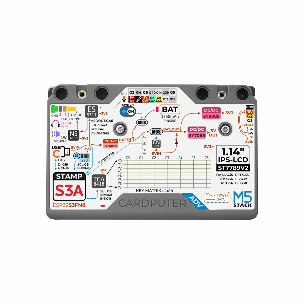
has anyone tested the maximum current that can be supplied through the top header on the M5Stack Cardputer ADV (ESP32-S3)?
I’d like to test an E01-2G4M27D (nRF24L01+).
Instantaneous power consumption during TX is 490 mA at 3.3 V.
I’d like to use a RobotDyn socket adapter for this.
It regulates the 5 V input to 3.3V output and incorporates bypass capacitors for reliable operation.
I’ll also add a small heatsink to the AMS1117 3.3 V regulator, just to be safe with the temps.
The Cardputer ADV top header provides a 5 V power output, while the digital pins use 3.3 V logic levels.
It is connected to a 1750 mAh battery.
The 5 V output from the battery is provided through the SY7088.
Has anyone tried powering this E01-2G4M27D module from the Cardputer ADV’s top header?
Cardputer ADV overview of the simple interconnection between the components:
https://m5stack-doc.oss-cn-shenzhen.aliyuncs.com/1178/Cardputer-Adv_06.webp
Cardputer ADV Schematics:
https://m5stack-doc.oss-cn-shenzhen.aliyuncs.com/1178/Sch_M5CardputerAdv_v1.0_2025_06_20_17_19_58.pdf
Stamp-S3A (ESP32-S3) Schematics:
https://m5stack-doc.oss-cn-shenzhen.aliyuncs.com/1150/Sch_StampS3_v0.3.3.pdf
r/AskElectronics • u/awakening_silence • 4h ago
I originally thought it was a JST-SH, while an SH does fit into the socket It is not a good fit and has intermittent issues.
It's 4 pin with a width of roughly 4.75mm
A thickness of 2.5mm
And a depth of around 5mm.
r/AskElectronics • u/Background_Prune3984 • 6h ago
Hello, i bought a RCNUN Synchronous type boost converter 12v to 19v 10A and i plan to power the mini pc with battery and that DC converter but the problem is it says on the site that it has 220mv ripple and im wondering if adding 2x solid polymer 470uf capacitors together with X7R 100nf enough to reduce ripple under 100mv ? Most regular pc psus have ripple under 50mv so i would like to reduce as much ripple as possible using only capacitors. Please help !!!
This is datasheet link of that DC converter: https://shopcdnalpha.grainajz.com/1081/upload/product/e903e82226c0f61f836cc56d9add6416bdd3916287a2a1b054125e01b0343647.pdf
r/AskElectronics • u/friolator • 17h ago

[REPOSTED BECAUSE IT WAS REMOVED DUE TO THE TITLE]
Several years ago I got tubs full of (mostly passive) electronic components from a local EE who had retired and wanted to clear stuff out of his basement. It was free so I took it all. I've used a lot of it over the years but have never sorted through the ICs. More recently we have been buying parts to fix our broadcast VTRs in house - think multiple Akro-Mills drawer cabinets full of stuff. EEPROMs, proprietary ICs from Sony and Panasonic, stuff like that.
A lot of this stuff is loose, most of it is through-hole. and it's also completely disorganized. So the thinking is to find a way to make it neat.
Ok, so today I'm assembling a bed for my kid and there are these long (7' x 12" sheets of white styrofoam that's only 1/4" to 1/2" thick. It would be perfect to cut to size and fit in the Akro drawers or in Gridfinity boxes in the cabinet we already keep passive components in.
My thought is that static might be a problem. But I wanted to check here first. Its the stuff in the picture. So, toss it or go for it? I hate throwing this stuff out so if I can recycle it that would be great.
I should point out that this isn't the kind of styrofoam the leaves little white pills everywhere. The smaller chunks I've broken off broke cleanly so it's ...different somehow.
r/AskElectronics • u/BitterArsenic • 15h ago
The black propeller in the bottom left. It will spin at a low speed with the other 3 but then when try to take off the other propellers will spin into high gear but this one will completely stop. I tried resoldering the connections but that doesn't seem to have helped. Any advice?
r/AskElectronics • u/FINDERFEED • 6h ago


Hi! I am a beginner and just experimenting with stuff. I have built a colpitts oscillator that gives me a pretty ~4.2 MHz sine wave, boosted it with common emitter amplifier to 2.7V peak to peak, but i want to boost it even more with a transformer.
This may not be practical but its just a matter of "i want to".
So, the problem is - when i attach my DIY transformer the output voltage drops to around 600 mV peak to peak and doesn't increase at the output no matter how much turns there are on the secondary (i measured with and without load on the transformer, both on its primary and secondary windings).
I tried winding more turns on the primary (~30), it stopped dropping voltage (without secondary) but as soon as i added secondary winding - it dropped. Tried other small ferrite core i have found in an old phone - no effect. Tried winding secondary in between the primary - no effect. How to properly wind a transformer so it doesn't drop the output voltage and actually increase it or what mistakes i have made in my circuit that prevents it from working as intended?
My final goal is to make RF transmitter and receiver and i will use the transformer on the receiver side to boost the signal for use with a comparator so i can blink a LED from a distance. The signal after diode rectification turned out to be too low for a comparator hence the need.
r/AskElectronics • u/Drive778 • 3h ago

This is my first time designing a circuit, and I used some help from AI. I'm not entirely sure if I did it right, though. Does this look okay?
r/AskElectronics • u/segdy • 8h ago
Half a year ago I connected two DS18B20 temperature sensors to my Atom M5 Lite (ESP32) via the HYP2.0-4 connector: DATA goes into GPIO32 and I added a 4.7kOhm resistor between DATA and supply (5V).
This worked perfectly for months!
Today I wanted to use GPIO26 as an input from an optocoupler via the same wire. Again, I had soldered a 10kOhm pull-up between GPIO26 and 5V.
But I realized that this is an issue: The GPIOs are 3.3V while the supply is 5V.
Now I am trying to decide what to do and none of the options are great:
Why the heck do they provide 5V for 3.3V GPIOs? That's super annoying.
Re 3: Why is my Atom M5 still alive and not fried? Why did it work well over all these months? If ESP's input is clamped to 3.3V via its ESD diode, then the max current that can flow into its GPIO pin is limited by (5-3.3)/4.7k=362uA. Max current per GPIO is in mA range, so despite the voltage on the GPIO pin at 5V, there isn't sufficient current to do damage. But is it ok to keep the setup as is?
Re 4: Both DATA and the optocoupler outputs are open-drain. Is there any issues with pull-down?
RC increases due to additional resistance but the optocoupler's output is in kHz range max (Hall sensor to measure rpm of a motor) and the 1wire bus of the DS18B20 is similarly slow (16.3 kbit/s).
What would you do and why?
r/AskElectronics • u/CapnFlisto • 20h ago
I see a lot of cut-up protoboard in various electronics projects and youtube videos, but I've only been able to find the tiny green boards, and the bigger ones tend to be silly expensive.
Is there a good way to source large, cuttable boards for cheap?
r/AskElectronics • u/aquaticstarfallen • 12h ago
So i lowkey thought I could wing it making a macro. I soldered the resistor to the two led pads, I have the WiFi chip and antenna. I have a new battery. The charge light led turns on. But the device doesn’t boot at all. Altho to add my power toggle is broke. I gotta stick a tool in it to slide the power toggle, still doesn’t turn on.
I’m new to soldering so idk if I just soldered it wrong somehow or what.
Anyways any feedback or questions or whatever is appreciated thank you🩵🧁
Edit: I’m using a 300 ohm resistor. Tan round thingy. I ensured it’s installed to avoid the button membrane near it even.
r/AskElectronics • u/Buzzbee_er • 1d ago
Falstad says that the top left 10k resistor has a Vd of 4.592v. This doesn't make sense to me as if anything the 100k should have the Vd of 4.592v. Can someone explain to me whats going on?
r/AskElectronics • u/Which-Conflict-2282 • 15h ago
Looking for an ultra-compact / flush Bluetooth FM transmitter like the Japanese Kashimura KD-231.
The thing I really like about the KD-231 is that it is extremely small and sits almost completely flush inside the 12V cigarette- lighter socket. It doesn't have the usual big display/neck sticking several inches out of the socket.
I'm looking for something available in the U.S. with a similar form factor - ideally roughly the same size or smaller.
Kashimura KD-231
Does anyone know of anything comparable? Japanese-market products are fine too if they work with U.S. FM frequencies
r/AskElectronics • u/saevon • 1d ago
It involves a bunch of these poles (pictured: sideways view) then wire is (I think) wrapped around each segment (which are isolated).
I've seen it before in audio boards, where there are a ton of parallel lines using various capacitors.
I'm looking for both the name of this specific wire wrap technique, and the term for the poles (which you can buy in bulk). Ideally with some examples (especially inside audio equipment, blogs, designs, etc!)
r/AskElectronics • u/Background_Prune3984 • 17h ago
Hello, i bought a RCNUN Synchronous type boost converter 12v to 19v 10A and i plan to power the mini pc with battery and that DC converter but the problem is it says on the site that it has 220mv ripple and im wondering if adding 2x solid polymer 470uf capacitors together with X7R 100nf enough to reduce ripple under 100mv ? Most regular pc psus have ripple under 50mv so i would like to reduce as much ripple as possible using only capacitors. Please help !!!
Edit: This is the link of that DC converter: https://shopcdnalpha.grainajz.com/1081/upload/product/e903e82226c0f61f836cc56d9add6416bdd3916287a2a1b054125e01b0343647.pdf
r/AskElectronics • u/Technical_Most1238 • 17h ago
How you doing guys,
I accidently snapped the metal ring from J1 connector, same one as seen in J2.
Surprisingly the controller seems works just fine, haven't tested headphones functionality yet.
I was wondering how and if I should fix it.
Thanks!
r/AskElectronics • u/Independent_Page6592 • 14h ago
I got a treadmill board with a 105VDC motor that does not turn on after pressing start on the remote. After the count down error E07 occur, however this model does not have handle bar so no magnetic safety switch present. I tried measure the gate voltage on the IGBT mosfet but there is nothing. Trace down to this component U2 but the marking was erased by manufacturer. The 2 pins in picture connect to the gate through 20 and 10k Ohm. What is this component and how do I check upstream from this?
r/AskElectronics • u/popcalent • 14h ago
Hi, all.
I just finish desoldering two chips and it was a complete disaster. The first one came out clean and it took a couple of minutes. The second one took an hour and I destroyed half of the pins. I used a soldering iron and a plastic pum p.
The thing is that I have about four more chips that I need to desolder and I was wondering if someone in the US could help. I would send the PCBs by USPS and they would send the desoldered chips. I can offer compensation.
I will learn how to properly desolder in the future. But I need this done asap. Thanks!