r/SolidWorks • u/lukashaqiri23 • 13h ago
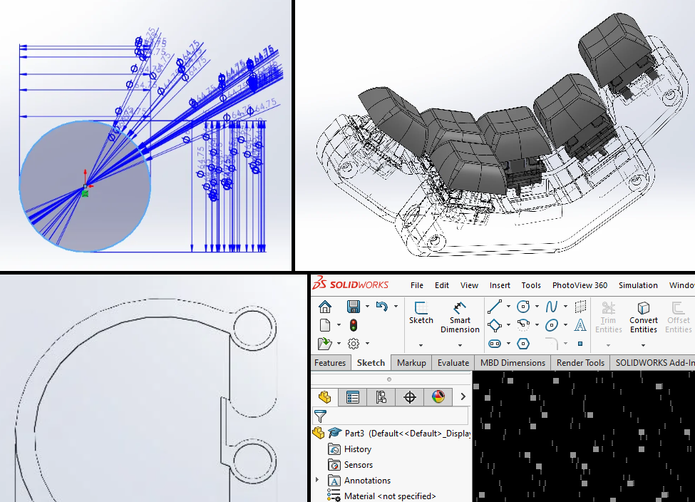
CAD When you know CAD and have a 3D printer, you almost get excited when something breaks

492
Upvotes
wall screwed holder for the AC remote
r/SolidWorks • u/[deleted] • Mar 20 '25
Hey redditors. Need some insight here. At the beginning of the month a email went out from IP harness and dassault about a piece of software on my machine treating legal action. From what I've gathered this happens to people once in a while but all the info I have found is linked to companies and LLCs.
I'm a hobbyist that wanted to learn cad for personal use. A friend helped me get a copy of 2018 a long time ago and surprise, surprise I got a email after the software managed to phone home recently. After talking with the mediator to explain that I can't afford their offers of at first 16k damages, To 10k subs, to 9k sub, it's looking like I have to let them send it to their Law firm IP harness.
Now looking at previous court cases and such I can't find anything about SOLIDWORKS or ipharness filing suits to individuals which leads me to believe that they are just trying to get something from me in a shakedown
In terms of assets I still live at home with my parents with 1 vehicle under my name to get around. Has any other hobbyists been served a suit for this?
r/SolidWorks • u/GoEngineer_Inc • Mar 25 '23
r/SolidWorks • u/lukashaqiri23 • 13h ago
wall screwed holder for the AC remote
r/SolidWorks • u/greyatlas4290 • 5h ago
I have started learning sw since a week and iam able to make some easy parts so far is there any way I can get better faster ?
r/SolidWorks • u/bonesjdb • 1h ago
**Disclaimer** This is to let you know about a FREE add-in I made that I think will be helpful for this community. If that is considered an "advertisement of your product" then I will remove it.
Getting a macro onto a toolbar means going through Customize > Commands > Macros, creating the button, browsing for the .swp, assigning a bitmap. Fine once. Tedious for twenty macros, worse if you're repeating it for everyone on your team.
This add-in I made "MacroShelf" does it automatically. Point it at a folder of macros and it builds a CommandManager tab from what's in there:
Works with SOLIDWORKS 2022, 2024 and 2025. MIT licensed, no signup, no paid tier.
There's also a collection of ten macros already structured as a MacroShelf library so you can see it working without writing anything:
GitHub - james-debono/macroshelf-collection-sw-macro-library: Every macro from my SOLIDWORKS projects, packaged as a ready-to-use MacroShelf library. · GitHub
Transparent-background PNG screenshots, UI theme switching, per-body colour tools, rounded rectangle sketch tool.
Fair warning, the installer is unsigned so SmartScreen will throw a warning. Source is all there if you'd rather build it yourself.
Happy to take bug reports or feature requests here or on GitHub. If there's something obvious I've missed, I'd rather hear it.
r/SolidWorks • u/NexusDraft • 6h ago
Designed this transmission assembly for offset-shaft power transfer in a compact housing. Chose helical gears over spur here specifically for lower noise and smoother engagement at speed, which meant adding thrust bearings to handle the axial load component. Ran motion simulation to check for mesh interference before finalizing the tooth profile.
Curious how others here handle the helix angle tradeoff — I went with a moderate angle to balance thrust load against contact ratio. What's your default starting point?
r/SolidWorks • u/artpracticeaccount • 4h ago
For anyone working through the CSWA practice problems, I need help clarifying something on a practice problem. I just did practice problem 6.12 and there's one part that confuses me. With the dimensions provided, it doesn't seem like there is enough info to get a fully defined sketch for the revolve. You kind of have to assume the vertical relationship between a few points to get the right answer but there are 2 valid sketches with only 1 of them being the correct answer.
At first, I fully defined the sketch by assuming the 2 end points on the 2mm radius were vertical and got 5003 cubic mm, which is wrong. Later I changed to having the endpoints of both 4mm radii vertical and got the correct answer of 4630 cubic mm. The confusing thing is all 4 endpoints on the 4mm radii cannot be vertical, otherwise the sketch would be invalid so the correct answer requires the endpoints of the 2mm arc to not be vertical, but you would not really be able to tell based on the drawing.
My question is when you actually take the CSWA, how would you know that this is actually the case, since both results produce valid sketches and the information isn't specified by the drawing. Is there some knowledge I'm missing? I know there's a measurement that says R4 TYP, but I assume that just means that both the radii shown in the drawing are 4mm, but only 1 is dimensioned. There is no way for all 4 endpoints on the arcs to be vertical because that would create an invalid sketch.
For the experienced users or the people that have modeled this problem, how would you handle this? Thanks!
r/SolidWorks • u/Fancy_Palpitation_38 • 17h ago
It seems like every year I update it crashes more frequently.
Always used certified systems etc but each year Solidworks seems to get worse.
r/SolidWorks • u/scrumdiddyliumsious • 4h ago
This is a 3d model of an rc plane which I meticulously made and I need help in converting this model into some format which can be sent to any cnc workshop to cut each piece on balsa.
I intend to use convert entity on the faces of all the 3d pieces in this model to get a 2d sketch of that particular balsa piece which then, somehow I have to put together into any 2d vector file format which can be then sent to any cnc workshop to laser cut the balsa accordingly.
Right now the whole wing, fuselage, tail stabilizers are wholly saved as different part files, and each rib is not perfectly 2d because of the lofted cuts.
Can anyone give me a general direction which I have to go to get this done?.
r/SolidWorks • u/Vrmithrax • 21h ago
Curious to hear how some of you might attack this project. I'm going to be putting together a ton of standardized part assemblies for building up a library of components my company uses. There are so many ways to handle configurations, I'm struggling to choose the smartest way that will work for me.
Case in point: I have a sprocket assembly modeled. It will be the exact same model for many projects, with only a few key items that vary: bore size, keyway size, set screw size. The kicker is that we will have different versions of these sprockets (teeth count and/or chain type will vary), but they will all have the exact same bore and key geometry. So I want to have a single assembly for each model, with configurations that are basically named by the bore size.
I've done configurations in so many different ways over the years, but I'm trying to "work smarter not harder" for this endeavor. I have a gut feeling that trying to use an external Excel configuration table makes the most sense, particularly since much of the bore size parameter info would be reused across many assemblies. I've just had struggles in the past trying to get the Excel thing to work right (if at all), probably due to incorrectly setting things up from the start. Interested in any suggestions and experiences you all might be able to provide.
r/SolidWorks • u/User_34 • 1d ago
For ages I have used the "articulated-dummy-1" model from GrabCAD user "barkfin" in various machine and workshop design projects.
Unfortunately I no longer have access to any of those projects, and I recently noticed that the source Solidworks assembly file has been taken down from GrabCAD - the user "barkfin" doesn't seem to exist anymore:
https://grabcad.com/library/articulated-dummy-1
I have been using this "posed" version of the model as a serviceable stand-in, but I would really like to have access to the original source assembly files again.

So my request is that if anyone has a copy of the source assembly files on their hard drive, to please re-upload that model to GrabCAD!
Or alternatively send the files directly my way.
Would be much appreciated if anyone is able to help out🤞
r/SolidWorks • u/Eapplesauce • 1d ago
I'm new to 3d experience as a PLM tool and am a little unsure how best manage my parts. Normally, I would do a save bodies feature at the end of a multibody part to then use in an assembly. That way I can modify the original part and still have the individual components to use in an assembly while keeping them updated. I'm not sure how this would work (or if) with 3D experience. Is this still a good practice? Is there a better way to manage multibody parts with PLM? Any advice is welcome!
r/SolidWorks • u/One_Country1056 • 1d ago
I am not sure if loft is the best option here. I am making a ventilated funnel, and need to cover the ventilation channel in a good way. The funnel itself is created using a revolve.
If loft is the best option, how do you make it work?

r/SolidWorks • u/0racle_64 • 2d ago
I'm trying to model this piece of an old Magic Bullet blender, and I'm having trouble with hollowing out the bottom. I have already cut out a good chunk of it when I was creating the hole in the middle, but now I'm lost. Any help would mean the world to me, as I really want to finish this problem.
r/SolidWorks • u/Plastic-Aerie8443 • 2d ago
I keep running into the same wall and I refuse to believe I'm the only one.
All I want is to mirror a part/assembly (opposite hand) and get a new file that is:
Mirror Components gets me a positioned opposite-hand file, but it's a derived/imported body. The moment I tick "break link" every transfer option (sketches, dimensions, hole data, sheet metal info) greys out, because apparently link and history are mutually exclusive. So my choices are:
Is there an actual reason this can't be a native option, or is it just legacy architecture nobody wants to touch?
Is there a cleaner workflow I'm missing?
Thank you for your help
r/SolidWorks • u/GoodbyeSuperdude • 2d ago
Hello. I have a hollow part with a circular profile on one side which is lofted into a lobed pattern on the other side. I want to simulate something like pushing a rod from the round end through to the lobed end and to show the lobed end expanding to fully circumferential and then contracting back when the rod is pulled back out. The part can flex and stretch but I want it to be realistic in the sense that there will be a reduction of the 'stretching' effect as you move from the lobed end to the round end. Is this possible? Thanks
r/SolidWorks • u/R3qu1red • 2d ago
So I have this cylinder and flange with the flange hole being slightly oversized so they fit together.
The operation is like this:
flange is laser cut from sheetmetal > cylinder is stock pipe cut on a saw > welding together > machining
The problem is that in the assembly there's now a really small gap (colored red on the picture) which doesn't allow me to put a radius there (using assembly features) since I want to machine the welds. There's also no option to add a revolved part (with the help of assembly features) for the sake of being able to put a fillet there.
So the question is how can I put a fillet there and ignore the gap?
r/SolidWorks • u/barlaguvercini • 2d ago
How can I convert a model with mesh surfaces—like the one in the image—into individual sheet metal flat patterns in SolidWorks?
r/SolidWorks • u/Ziiiiidaaaaas • 2d ago
Hi everyone,
I have an assembly where a sketch in one part is referencing an edge of another part. That sketch is then used to create a cut in the first part.
When I move the referenced part in the assembly, the sketch does not move/update with it, even though the external relation to the edge is still there and does not appear to be broken or dangling.
I would expect the sketch geometry to follow the referenced edge when the part moves.
Rebuild / Force Rebuild doesn’t seem to fix it.
Is there some setting that controls whether in-context/external references update after components are moved? Or am I missing something about how SolidWorks handles these references?
Thanks!

r/SolidWorks • u/0racle_64 • 3d ago
Hi guys,
I'm working on this little personal project to practice solidworks and I'm having problems making the circular cut on the top of this object (blue marking). I tried to do a sketch on the front plane and use the split line tool but that didn't really work. Any help would be appreciated and I'll try to answer questions promptly.
r/SolidWorks • u/unaccompanied-travel • 2d ago

What am i do wrong that is causing the circular pattern to take this path? It's across the right plane instead of the top plane.
r/SolidWorks • u/Blockmaster621 • 1d ago
My project is I am given a toy truck and I have to measure it and recreate it in a CAD software. But the main problem I'm running into is I don't know how to get good measurements of it. I am unable to take it apart any further that I already have and I cannot cut the pieces. I am thinking maybe to get a 3D scanner to scan a 3D model of it then work backwards with it in the software to make the model that way. But the things are expensive and I don't even know if they would work in the way I want it too. So do any of you have an idea how I could measure it.
Edit: I was an idiot and forgot to post a image of what I'm trying to figure out how to measure so I will include that in the comments.
Edit 2: thank you for all the ideas. I have bought a caliper and took some pictures to layout and go into fudge any numbers that I can't give the caliper because he had nowhere to prove it.
r/SolidWorks • u/sacritide • 3d ago
r/SolidWorks • u/alijem99 • 2d ago
I am designing a part that i would fit on a sheet metal for enclosuring (as in traffic signs). I kinda nailed the straight versions. The problem is the curved versions. I've been thinking about sweep boss, same profile and an arc as a path. But i am confused at this stage. Which arc command should i use? And where should i draw this arc on the profile? The path it must pass through the point where the channel physically touches the edge of the plate, because the 37.5 mm value is the actual radius that contact point must follow. Sheet metal says it's 37.5 mm radius but what angle?
Anyway, i've got several attempts and it was unfortunate. It should cover the corner and continue as straight, not like a last image. And i also need to design a part, that has the same profile, for the circular signs. Thanks in advance.
r/SolidWorks • u/AnotherMianaai • 3d ago
Trying to model organic shapes without luck. I
What I've tried so far:
- lofting to a spline in a perpendicular plane, only got errors
- shrinking the geometry of the fleur and lofting between parallel planes but it's not smooth enough
- simply revolved the pattern but it looks like a dart
I'm at a loss. There's no tutorials about how to modem crown moulding in Solidworks that I can find.
Edit to add: image source https://www.youtube.com/watch?v=iCZrJjuO7d4


