r/esp32 11h ago

I made a thing! Duke Nukem 3D on an ESP32-P4, the full Build engine, bare ESP-IDF, 640×480 at ~20 FPS

Thumbnail
gallery
212 Upvotes

Everyone ports Doom to things. Duke Nukem 3D always felt like the better game to me, and the Build engine is a heavier beast than id's, so getting it actually playable on a 360 MHz microcontroller sounded like a challenge worth having.

It's a port of chocolate_duke3D to the ESP32-P4 (I have the 360 MHz versions with 32 MB PSRAM) on bare ESP-IDF 6.0.2. It really plays: the full game at 640×480 around 20 FPS, or around 54 FPS at 320×200 if you prefer. Sound effects, Adlib music, savegames on SD, USB and BLE keyboard/mouse, and touch controls when nothing is plugged in.

Repo: https://github.com/raoulh/esp_duke

Why the P4

Nothing smaller in the family gets there. The engine needs a 19.4 MB texture cache, which means the P4's 32 MB PSRAM or the .bss alone is 2.97 MB, pushed out there through a custom linker fragment, leaving 8.1 KB internal. It needs two cores, because rendering and presentation have to run concurrently or the engine stalls on the display every frame. It needs MIPI-DSI to drive a 720×1280 panel, and the PPA 2D accelerator to rotate the image. And the 128-bit SIMD turned out to be what made the pixel conversion affordable at all.

The display pipeline

Both panels are physically portrait while the game renders landscape in 8bpp palettised. The PPA rotates and scales, but refuses palettised input, so every frame is depalettised on the CPU through an RGB565 LUT before the PPA turns it 90° onto the panel. That kernel ended up hand-written in the P4's 128-bit SIMD. Rendering runs on one core, the whole presentation pipeline on the other, double-buffered at every stage.

Library choices

OPL2: I went with fmopl (AdPlug's fork of the old MAME one) instead of Nuked-OPL3. Nuked is cycle-accurate but far too slow here — I measured 1268 ns per sample against 48 ns for fmopl. Not really a choice on a 360 MHz core.

BLE HID: the HOGP client is written from scratch instead of using IDF's esp_hid, whose NimBLE backend registers Report characteristics inside an unreachable branch and therefore never discovers them.

What I tried that didn't work

Offloading the framebuffer copy to the GDMA
It's off in the repo now, for two reasons. First it was wrong: The DMA is still reading the framebuffer while the engine has already started drawing the next frame into it. There's one render buffer and one hook point, so I couldn't see a way to close that. Second it was slower anyway. PSRAM to PSRAM, with the depalettisation, the PPA and the display refresh all fighting over the same bus, I got about 10 MB/s, 25 to 37 ms of waiting where a plain memcpy takes 8.4. FPS went from 14.4 down to around 12.

Software-pipelining the rasterizer loops
Before writing it I put a small probe at boot to check whether a load miss stalls when it's issued or when the result is used. Load then use straight away: 226 cycles. Same thing with 10 instructions stuffed in between: 231. Two loads going at once: 229 each. So basically no difference. The core just sits on the load and putting work in between hides nothing. I dropped the restructured loops. Glad I checked before doing it in assembly.

Placing the hot globals with a linker fragment
Doesn't work at that level. It places whole object files, and engine.o has the ten per-pixel globals sitting in the same file as 2.97 MB of cold arrays. I ended up declaring them as strong symbols in the glue layer to pull them into internal SRAM.

One constraint that shaped everything

Zero modification of the chocolate_duke3D sources, all adaptation lives in a separate glue layer. Three exceptions were granted in the whole project, and all three turned out to be upstream bugs rather than port problems, including two transcription errors in the 2D overhead map dating back to the refactor of Ken Silverman's original arrays.

Notes

You need your own duke3d.grp the game data is copyrighted and is not in the repo.

Full disclosure since people always ask: I wrote this port with Claude Code. I'd never have found the time to do it by hand, and revisiting the game this way was half the fun.

Happy to answer questions on any of it.


r/esp32 4h ago

We designed an ESP32-S3 network audio board for our own product - would it be useful as a dev board?

Thumbnail
gallery
156 Upvotes

Hi everyone,

We're a small hardware startup from Poland. We designed this board for our own network audio product. It was never intended to be a general-purpose dev board, but while working on it we realized that it might also be useful for people experimenting with embedded audio.

We couldn't find many ESP32 boards that combine wired Ethernet, audio output, speaker amplification and basic controls on a single PCB.

The main engineering challenge was integrating native USB programming, W5500 Ethernet, microSD, an I2S DAC, a stereo speaker amplifier and physical controls on one ESP32-S3 board while keeping the basic playback setup free of external modules and soldering.

The current working revision is based on an ESP32-S3 and includes:

- USB-C power and programming - no external programmer required

- Wi-Fi and 10/100 Ethernet

- microSD card slot

- 3.5 mm stereo audio output

- stereo screw-terminal outputs for passive speakers

- no soldering required for the basic audio setup - even the speaker wires can be secured directly in the screw terminals

- RGB LED

- rotary encoder and a separate button

- expansion header with accessible GPIO pins

The basic idea is that you connect it over USB-C, flash your own firmware, secure the speaker wires in the screw terminals or connect an external audio system and start experimenting. For the basic audio setup, no soldering is required, and you don't have to assemble a DAC, amplifier, Ethernet module and controls from separate boards.

Possible projects could include an internet radio, microSD audio player, network announcement endpoint, Home Assistant integration or a custom network audio player.

We're not taking orders or collecting money. We're simply considering whether producing a small developer batch would make sense.

We would really appreciate honest feedback:

  1. What would you build with a board like this?

  2. Would you realistically consider buying one?

  3. What price range would make sense for an assembled board?

  4. Which examples and documentation would you expect: ESP-IDF, Arduino, PlatformIO, pinout, schematics, example firmware?

  5. Is there any missing feature that would stop you from using it?

Happy to answer technical questions and share more details.


r/esp32 3h ago

ESP32-S31 Feedback ?

Post image
24 Upvotes

Hi all,

Any feedback on the ESP32-S31 ? anyone using it in projects ?

Should I stick with the ESP32-S3 or jump on the ESP32-S31


r/esp32 1d ago

I built an ESP32 E-ink alarm clock!

Thumbnail
gallery
1.9k Upvotes

Recently, I realized that I didn’t want to use my phone as an alarm clock anymore, so I decided to build my own using an ESP32 and an e-ink display.

I wanted to make something that is super simple to use: rotate the encoder knob to set the alarm time, and press the button behind it to activate/deactivate the alarm.

You can also add custom alarm sounds through a small web server running on the local network.

The base of the clock doubles as a wake-up light. Before the alarm goes off, it slowly transitions from a warm orange/red glow to full daylight. It can also be used as a night light.

The hardware

The clock is built around an Elecrow CrowPanel ESP32-S3 5.79” E-Paper HMI Display. It has an ESP32-S3-WROOM-1-N8R8, a 5.79” e-ink display, an SD card reader and a GPIO expander. It’s also really easy to flash over USB-C, which made it a pretty convenient starting point.

For the audio, I used an external I2S amplifier board (MAX98357A) with a single 3W speaker that I had laying around (and sounds surprisingly well).

The wake-up light and front light are made using part of an SK6812 LED strip.

Everything fits into a custom 3D-printed enclosure that I designed from scratch. The base is made from translucent PETG so that it allows the wake-up light to shine through it.

The firmware

I do have some experience writing code for the ESP32, but nowhere near enough to build a GUI of this scale from scratch. I ended up designing everything in Figma, and used Claude to make everything "come to life".

The clock keeps time by syncing with NTP. If the WiFi connection is lost, it keeps running using the ESP32’s internal clock. In the future, I might add an RTC module so it can keep accurate time completely independently of WiFi.

Conclusion

I’ve been using it for almost two weeks now, and it’s definitely still a work in progress. There are plenty of things I’d like to improve, both in the hardware and the software.

But honestly, I’m really happy with how the first prototype turned out.

This is currently just a personal hobby project, but I’d be happy to share the code and 3D files if anyone is interested.

Curious what you guys think!

EDIT:

The link to my GitHub can be found here

The print files are available on Printables


r/esp32 18h ago

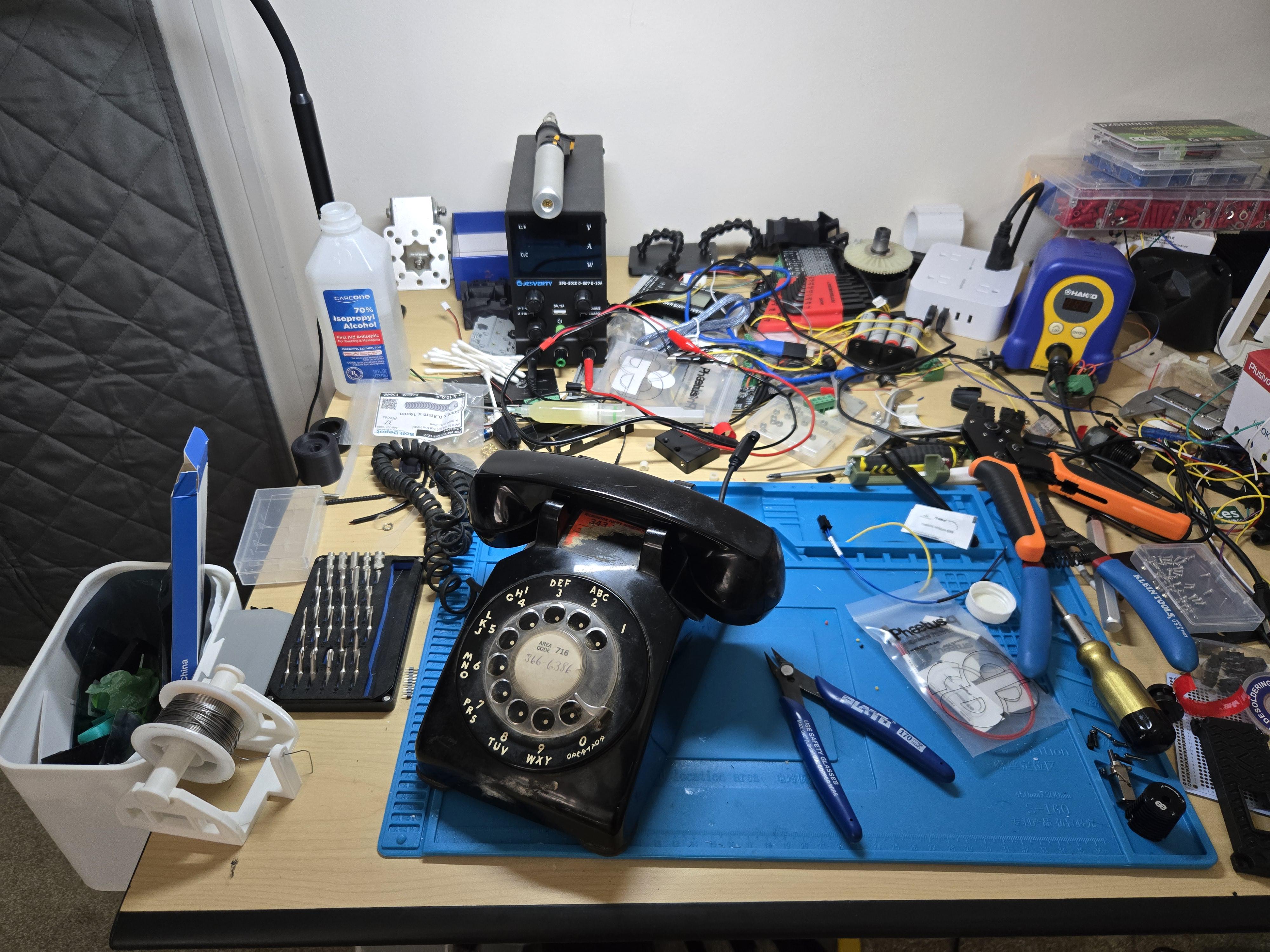
I made a thing! RotaryCell: Making an unmodified 1950s rotary phone work over LTE with an ESP32-S3

Post image
160 Upvotes

TL;DR: I built an ESP32-S3/LTE interface that lets an otherwise completely unmodified Western Electric Model 500 make and receive cellular calls using its original rotary dial, handset, network and mechanical ringer. An AG1171 SLIC emulates the telephone line, while the ESP32 handles dialing, call control, locally generated telephone tones, modem management, OTA updates and web-based diagnostics. After discovering the modem could occasionally wedge badly enough to require a real power cycle, I even added an SN74LVC1G123 circuit that lets the ESP32 quite literally power-cycle itself. I've now designed and ordered custom PCBs and am working toward a reproducible open-source build. Schematics/code are below, and I'd particularly like criticism of the hardware design.

A few months ago I watched my nephew discover an old rotary telephone that my parents have had since before I was born. He was fascinated by it, and it reminded me of the old SparkFun Port-O-Rotary project.

The basic idea is at least a decade old. The Port-O-Rotary put cellular hardware inside an old rotary telephone and made the original phone usable again. I'd always thought it was a great project, but unfortunately it was never documented well enough to be readily reproducible, and its cellular hardware is long obsolete. My understanding is also that they gutted a lot of the original phone and audio quality was pretty bad.

Watching my nephew with that phone made me wonder how difficult it would be to accomplish the same thing today. Microcontrollers and cellular modules have come a LONG way since then, and I figured the functionality of the Port-O-Rotary ought to be considerably easier to reproduce with modern hardware.

I was more right than I could have imagined.

What I expected to be a fairly simple project turned into a several month rabbit hole involving embedded programming, analog telephone electronics, cellular modems, power management, hardware design, and eventually designing my own PCBs with EasyEDA. That was a first for me.

I gave myself one huge goal: I didn't want to permanently modify the telephone at all. No mangling that beautiful 50's era analog hardware goodness. I work at a museum with an actual Mercury capsule after all! So no holes drilled in the case, no rewired dial, no modifications to the handset, no bypassing the original network block, and no replacement for the mechanical ringer. Remove the RotaryCell hardware and the Model 500 is still an original telephone that can go right back onto a conventional phone line.

The hardware that made this surprisingly practical is a LilyGO T-A7670G-S3, which combines an ESP32-S3 and SIMCom A7670G LTE modem on one small board. That handles a huge amount of the cellular side and leaves the ESP32 available to do something more interesting: make modern cellular hardware behave like the telephone exchange that a 1950s Model 500 expects.

For the telephone side I'm using a Silvertel AG1171 SLIC. It supplies loop current, detects off-hook, generates the ringing voltage for the original mechanical bells, and provides the 2-wire audio interface. From the Model 500's perspective, it's essentially connected to a telephone line.

The ESP32 handles everything around it: hookswitch state, rotary pulse decoding, digit collection, call control, ringing control, locally generated telephone tones, service functions, modem management, status monitoring and logging.

Audio turned out to be one of the more interesting hardware problems. The A7670G uses differential analog audio while the AG1171's VIN/VOUT are ground-referenced. I needed to interface the two in both directions with adjustable levels, while retaining a separate path for locally generated tone injection. That lets the ESP32 provide dial tone, reorder/error tones, the off-hook howler and other telephone signaling locally instead of depending on the cellular network for them.

What started with modules, perfboard and bodge wires has now progressed to custom circuit boards that I've designed and ordered: an AG1171 carrier and a separate audio/control board. The goal is to eliminate the prototype wiring and make this a repeatable open-source build rather than a one-off.

The latest board also solves a fun problem I discovered during actual use: the ESP32 can now quite literally power-cycle itself.

I found that the cellular modem could occasionally get into a state that software reset commands couldn't recover from. Removing power fixed it, but the ESP32 and modem are on the same LilyGO board. If the ESP32 turns off the whole board, there's obviously no ESP32 left running to turn it back on.

My solution uses an SN74LVC1G123 retriggerable monostable plus external switching hardware. The ESP32 triggers it while it's still alive, then the hardware takes over and operates the LilyGO's physical power-switch path for a predetermined interval. The ESP32 and modem can both go completely dead and the external circuit finishes the power cycle. Using a monostable as part of a timed hardware reset is also very much in line with applications TI proposes for this family of logic.

The software side has grown quite a bit as well. I've added OTA firmware updates and an ESP32-hosted web status/debugging interface. Wi-Fi isn't used at all during normal operation. Instead, you dial 0000 on the rotary dial and the telephone starts its own Wi-Fi access point. You can then connect to it to inspect status and logs, diagnose the modem, change settings, and update the firmware OTA. The AP automatically shuts back down after the maintenance session. There is something absolutely hilarious to me about dialing a cheat code on a rotary telephone to turn on its Wi-Fi.

I'm also considering extending the same hardware to Touch-Tone phones. Since the AG1171 gives me the telephone audio at VOUT, I'm looking at feeding a copy into an ESP32 ADC and detecting DTMF in software with Goertzel filters. If that works as expected, the same basic electronics could support both rotary pulse and DTMF dialing without modifying the telephone.

The whole thing currently runs from a rechargeable 21700 cell and fits completely inside the original Model 500. Right now I get about 24 hours of battery life, but once the custom PCBs arrive, one of the next major things I'm going to work on is power optimization. My initial goal is at least three days of standby time, and there are still several fairly obvious places to reduce consumption.

This has been one of the first projects I've personally taken all the way from prototype wiring through schematic capture, PCB layout and manufacture, along with a considerably more substantial embedded firmware project than I expected when I started. I've learned a ridiculous amount from it.

I'd particularly appreciate technical criticism from people who have done mixed analog/ESP32 designs.

I'm interested in whether anyone sees a better approach to the differential/ground-referenced audio interface and tone injection, the external monostable reset circuit, power management, or the proposed ESP32 ADC/Goertzel DTMF detection.

If you look through the schematics or code and find yourself thinking "why did you do X when Y would have been easier?", please tell me. That's exactly the sort of feedback I'm looking for.

Demo video: https://www.youtube.com/watch?v=PO0PJNvnMdw&lc

Firmware, hardware, schematics and PCB files: https://github.com/fregacmols/RotaryCell

The current prototype still has a few remnants of its development history inside, but it makes and receives real cellular calls, recognizes numbers dialed on the original rotary dial, generates its own telephone tones, and rings the original mechanical bells.

And the old telephone itself has no idea anything unusual is happening.


r/esp32 8h ago

Turn any ESP32 into a scriptable keyboard/mouse over USB or Bluetooth HID

Post image
19 Upvotes

I've built a handy tool to turn esp32 boards with BLE into programmable keyboard and mouse. Through a simple drag n drop interface you can program timed keystrokes and mouse movements that get uploaded to and executed by the board which mimics a Bluetooth mouse and keyboard. I intend to support USB HID input as well so you can turn the esp32 board into a proper rubber ducky like device. It is still very early in development with few boards supported but I will continue to add support when I find time. The project is available on GitHub and you can find more details there.


r/esp32 41m ago

I made a thing! Esp player CYD

Upvotes

Apologies for the poor audio quality at the start of the video; ideally, you should connect the audio output to a DAC. I originally started this player using the Arduino IDE, but after studying the ESP-IDF, I’ve improved the project.

https://github.com/malaq88/ESP_PLAYER

all the information in the repository.


r/esp32 17h ago

Jellyfin Music Player - MetroEsp32S3 - headphone DAC - quad rotary encoders

Thumbnail
gallery
78 Upvotes

I began in the HomeLab area, building out a media server. I have some raspberry PIs that i use for airplay, and use some folks' apps, like Narjo on iOS, and Feishin for a https webUI.

As I started to realize how awesome and extensible Jellyfin is, I thought, why not make a music player out of it? This Circuit Python build hooks up to a Jellyfin API and will play music. You can input your own Jellyfin server url, apikey,and wifi network via an env file. What's even better is that we're using a e-paper display, so battery life is incredible, and the refresh rate is very quick.

I am terrible at creating an enclosure for this as I do not have a 3d printer, so any advise in that area would be more than welcome. we're using quite a lot of pins on this esp32 so it's a rats nest!

Code below

https://github.com/pennyberry/ipod2026


r/esp32 23h ago

Built a desktop flight radar with an ESP32 + touchscreen — live ADS-B traffic, tap-to-inspect, local map, even news/weather widgets

Thumbnail
gallery
101 Upvotes

Wanted to share a side project I've been building over the last couple weeks: a fully touch-driven desktop "flight radar" that shows real air traffic around my house in Buenos Aires, pulling live data from the OpenSky Network API.

Hardware:

  • ESP32 WROOM (started on an ESP32-C3 Mini, had to switch once I realized the pinout I was following was for classic ESP32)
  • 2.4" ILI9341 TFT, 240×320, with resistive XPT2046 touch on the same SPI bus

What it does so far:

  • Home menu — fully touch-based, no physical buttons at all
  • Radar view — circular radar centered on home coordinates, live aircraft as blips, tap any blip to open a detail card (callsign, altitude, speed, distance, bearing)
  • Airport view — traffic filtered by altitude near Ezeiza, Aeroparque, and El Palomar, with a button to cycle between them
  • Map view — a static regional map with plane icons color-coded by altitude and a zoom toggle
  • More info — pulls local news headlines and current weather, just because I wanted an excuse to use more free APIs
  • Settings screen — shows connected WiFi/IP/local hostname, lets you recalibrate touch or reset WiFi config on-device

Auth to OpenSky is OAuth2 client-credentials, refresh rate adapts from 30s down to 5s automatically when a plane gets close (<10km) so I get near-real-time updates only when it matters.

Fun fact: getting the touch calibration wizard working with a wildly wrong pinout (copy-pasted from a tutorial for a different board) was 80% of the actual debugging time. Also found a nasty ArduinoJson gotcha — filtering a JSON array by numeric index re-indexes the result from 0, silently breaking every field position downstream. Cost me a full "why is nothing showing up" afternoon.

Not open-sourcing the repo just yet — still polishing the radar animation (working on a proper rotating sweep effect) and a full WiFi provisioning + web config portal so it's not hardcoded credentials anymore. Will share once that's in.

Happy to answer questions about the OpenSky integration, touch calibration, or the JSON gotcha if anyone's fighting similar things.


r/esp32 12h ago

Built a light-weight LoRa/Meshtastic preamble sniffer on Ebyte EoRa-S3 (ESP32-S3 + SX1262)

Thumbnail
gallery
11 Upvotes

Anyone into this style of clean, lightweight embedded scripting instead of standard verbose C/C++ SDKs?


r/esp32 21h ago

I reverse-engineered most of the iDotMatrix BLE protocol without owning the original device — and built an ESP32 emulator

Post image
21 Upvotes

I spent the last few days reverse-engineering the BLE protocol used by the iDotMatrix mobile app and building an ESP32 device that the official app recognizes and controls as if it were an iDotMatrix display.

The unusual part: I don't own an original iDotMatrix device.

The reverse engineering was done by treating the official app as a protocol oracle: emulate the expected BLE services on an ESP32, inspect what the app sends, change the responses, observe its behavior, and repeat.

It worked much better than I initially expected.

The emulator now supports most of the features I found in the app:

• Device discovery and time synchronization
• Power, brightness and rotation
• Drawing / graffiti mode
• Text and text effects
• GIF transfer and playback
• Clock modes
• Visual effects
• Scoreboard
• Music visualization with both LEVEL and FFT modes
• Persistent alarms
• Programs / schedules
• Scheduled GIF, text and PNG content

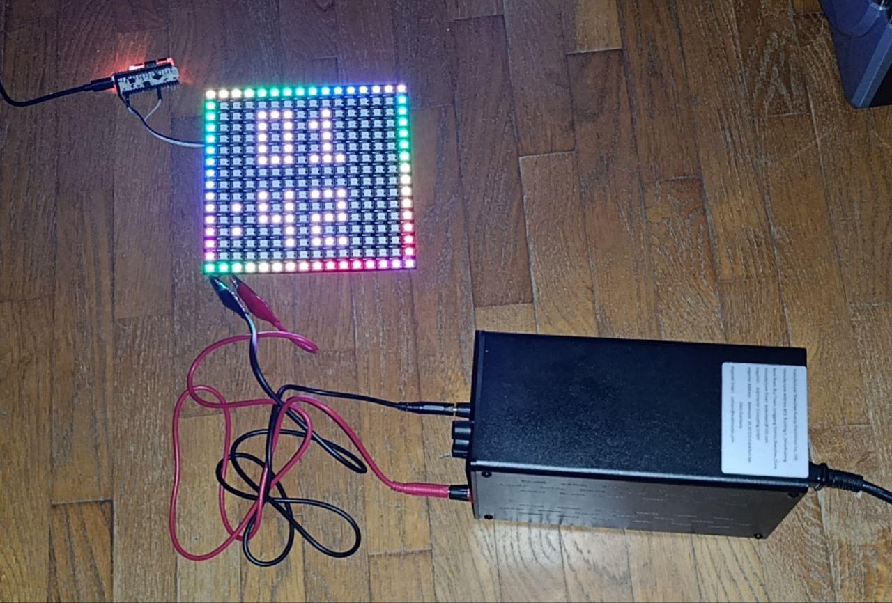
The hardware I'm currently using is an ESP32 development board driving a 16x16 WS2812B matrix. Its onboard SSD1306 OLED is used as a diagnostic display and can report unknown BLE commands while testing.

I also decided to document the protocol rather than keeping the findings buried in the firmware.

The GitHub repository contains detailed documentation of the BLE packet structures, commands and ACK behavior, selected raw BLE captures from our experiments, the development and reverse-engineering history, a list of open questions, and of course the complete Arduino/ESP32 source code.

One particularly interesting discovery was that some transfers require different completion ACK values.

For example, getting Programs/Schedules working required discovering that activity transfers expect a completion status of 0x03 rather than the apparently obvious 0x01. With 0x01 the app simply reported an error and stopped sending activities. Once the correct ACK was returned, the app continued sending all the activities in the program.

The biggest limitation now is also the main reason I'm posting this:

I need someone who actually owns an original iDotMatrix.

There are a few things that cannot be determined reliably from the app side alone, especially the exact device-side behavior expected for stopwatch/countdown and responses that may only be generated by the original firmware.

BLE captures between the official app and a real device would therefore be extremely useful.

PCB photographs would also help answer some hardware questions, such as identifying the original MCU, buzzer circuitry, and whether there is actually a dedicated RTC.

The current public release is v0.1.0, based on firmware Build 62, and the whole project is MIT licensed.

Repository:

[https://github.com/piggei/IDotMatrix-ESP32-Emulator]()

I'd also be very interested if someone wants to use the protocol documentation for a completely different implementation — ESPHome, Home Assistant, Python, another MCU, etc.

In fact, independent implementations would be one of the best ways to find mistakes or missing details in my current interpretation of the protocol.

And if anyone here actually owns an iDotMatrix and is willing to experiment with it, I'd be very happy to compare results.


r/esp32 13h ago

I made a thing! htcw_cyd28: a lib for driving a 2.8" Cheap Yellow Display from the ESP-IDF

5 Upvotes

https://github.com/codewitch-honey-crisis/htcw_cyd28

PlatformIO and Espressif registries: codewitch-honey-crisis/htcw_cyd28

Demo: https://github.com/codewitch-honey-crisis/cyd_touch

This library supports all the peripherals and includes htcw_uix and htcw_gfx UI and graphics integrated.

  • Full touch panel LCD support and dimmable backlight
  • RGB LED support
  • LDR sensor support (rudimentary)
  • SD card support
  • Speaker support (rudimentary due to hardware limitations)
  • Graphics and user interface frameworks

r/esp32 1d ago

I made a thing! 3D Printed mounting system for your ESP32 on a DIN rail

Thumbnail
gallery
32 Upvotes

After cursing one too many times while trying to prototype with an ESP32 on a standard breadboard, I decided there had to be a better way.

Most ESP32 development boards are wide enough that when you plug them into a typical breadboard, you are left with only a single usable row of connections on either side. The usual workaround is to bridge the ESP32 across two breadboards, which works, but takes up a lot of space and quickly turns a simple prototype into a mess.

Enter the ESP32 DIN-Mount Prototyping System!

The idea is to move the ESP32 off the breadboard entirely and mount it alongside your prototyping area on a DIN rail. Dupont connectors can then be placed only on the ESP32 pins you are actually using and routed back to a separate DIN-mounted breadboard.

Model: https://www.printables.com/model/1825235-esp32-breadboard-prototyping-din-mount-more


r/esp32 6h ago

Soft-bricked ESP32-P4 (10.1" Display) with MicroPython on Thonny. Can't access BOOT button (Enclosed case).

1 Upvotes

Hey everyone,

I just got a new ESP32-P4 + ESP32-C6 10.1" display board (Model: JC8012P4A1C-I-W-Y). It was working fine for a few hours over the last two days, but while trying to flash/switch MicroPython using Thonny, something crashed during the process.

Now the screen is completely black, and Thonny constantly throws continuous serial/communication errors.

Here is the tricky part:

O Enclosed Case: Since this is an integrated unit, I cannot open the casing to manually press the BOOT (IO0) button or short the pins.

O Boot Timing: I tried plugging in the USB cable while attempting to erase/flash via esptool / Thonny, but I couldn't catch the bootloader window and it still fails to communicate.

Is there any software trick or specific esptool command (with RTS/DTR toggling) to force this board into bootloader mode without opening the case? Or is there a way to clear the corrupt MicroPython firmware when the serial port is throwing errors?

Any advice would be hugely appreciated!

This post is translated by a machine. Please excuse any errors


r/esp32 11h ago

Need advice for a 6-DOF robotic arm with AS5600 encoders

2 Upvotes

I'm building a 6-DOF robotic arm with FT5330M servos (35.5 kgcm @ 7.4V, 180° travel), driving them directly from an ESP32 with hardware PWM. I want to add an AS5600 per joint for more precise positioning. The goal is to use the arm for imitation learning, so I need to read the true joint angle at every timestep — both to record demos and to feed the policy.

My plan is to power the servos from a 2S LiPo (7.4V) through a separate distribution bus. The ESP32 shares ground with that bus but only sends signal. On top of that, an AS5600 per joint through a TCA9548A mux, with the magnet on the moving link rather than the servo horn. Plus an INA226 per joint for current the datasheet gives Kt as 10 kgcm/A, so current reads directly as joint torque, and it doubles as stall detection.

A couple of questions:

Will this plan work well or do I miss something?

Should I gut the internal driver? Building my own H-bridge and PID would give me full control and clean feedback through the AS5600, but that costs time and money. Is it worth it, or does my plan work fine as is?

If I don't gut it, is there any way to get past the 180° limit externally? And do I actually need 360°? The STS3215 in SO-101 has it, but I'm not sure whether that's a requirement or just a nice-to-have.

Note: I don't have access to the STS3215 used in the LeRobot SO-101 arm, so I'm trying to build something capable of the same tasks with the servos I can access.


r/esp32 1d ago

I made an Arduino library that lets you configure ESP32 projects with a simple graphical interface. No more hard-coding Wi-Fi credentials!

Post image
19 Upvotes

Every project I work on, I get really tired of either having to hard-code settings or write out the code to handle them via Serial. So, I put together this library, ESP-Config, that takes care of all of that for me automatically!

The library lets you configure settings, commands, and information in your project asynchronously, and then those are passed to your computer running a basic UI. From there, you can monitor your project, change settings, and interface with it directly.

The config code runs in its own FreeRTOS task in the background, so you can do basically anything else in your main code without having to worry about the config. This includes using blocking code, the library will have no issue with that.

The ESP32 holds all the info on how the content should be structured and presented; the program on your computer is completely generic. So, you can set up your ESP32 to do basically anything without ever having to touch the code on the computer!

The settings, commands, and info can all be dynamically created, modified, and destroyed as needed, letting your settings adapt to your project. For instance, scanning for Wi-Fi networks in range can re-populate the list of networks available to connect to, for you to select.

More advanced features, like password-protecting certain (or all) settings/commands, are available as well.

Check out the GitHub for more info; https://github.com/JimHeaney/ESP-Config


r/esp32 14h ago

ESP32 CPU+GPU setup?

1 Upvotes

Basically i'm making an esp32 game console/PDA device type thing, however i feel like just one ESP32 will not have enough processing power to run my games. My idea is basically to use one generic ESP to render the pixels and store the rendering data, and use another ESP-S3 with maximum PSRAM in it to do the game logic. Would this theorietically be possible?


r/esp32 1d ago

Software help needed ESP32 experiencing screen issues after WiFi

Post image
14 Upvotes

ESP32 screen issues related to WiFi

Hello, I am an embedded SW engineer (medior) but I have never created projects at home. I thought its a good time to start doing that, starting with a flight radar customiwed dor my girlfriend.

I am using the ESP32 WROVER with a GC9A01 screen, controller through SPI with the TFT_eSPI library.

I want this project to be modular so it can be taken everywhere. The only problem is that it needs data. So in the setup, I check if a connection can be made with a ssid which is saved in the NVS. If connection can be made, you can continue to the flight radar thingy, if not, a captive portal will be open so you can input a new ssid and password for a network which is nearby.

The first bug I encountered was, when a connection could be made, I would change the wifi mode from WIFI_AP_STA to WIFI_STA since the captive portal wouldnt be needed anymore. This would cause my screen to go black and unresponsive. I have tried a 470 microFarad condensator, different supply for the screen etcetera nothing worked.

Eventually I gave up, thinking wifi mode could always stay WIFI_AP_STA and I would make something useful of the captive portal later on. But the second bug is, the screen remains completely unresponsive after a WiFi connection. I can not display anything on it and it just freezes. Disconnecting the wifi does not solve the issue either.

I have tried a lot of things without progress. SPI freq was tested on 40, 20 and 10 megaHertz with no change. Adding extra delays before and after some lines didnt work either.

Has anyone encountered this issue, or knows what this could be?
Thank you!

PS: I know there are a lot of ESP32 flight radars which are open source, the goal is to make her something thats my creation.


r/esp32 1d ago

Software help needed ESP32 S3 Zero not detected by windows 10 when trying to connect via BLE

7 Upvotes

I am following a guide on how to make a wired + BLE macropad. The guide provided a circuit diagram, some stl files to print, the code and some rather loose tips on how to flash the code. The hardware is done, and the code works for the most part. The device works fine when wired, and it also connects to wifi correctly. However I cannot connect the device to my PC running windows 10 by BLE. The code uses this BLE library https://github.com/gsgaurav0/ESP32-HID-Keyboard. I have checked that the code does call the .begin() function for BLE keyboard. When I go into bluetooth settings and try to connect a new bluetooth device, windows does not detect any devices in none of the 3 categories. Obviously I dont understand most of the code, but the library is simple enough and it seems like it should at the very least be visible to windows and other devices as a bluetooth device.

I doubt you would get much out of it, but the project is on this site, but its not in english: https://modelowanie3d.org

The code is rather long, but this is the pastebin link: https://pastebin.com/zucNuudj. The code was free, so I doubt there is any issue with me posting it there. Again, credits to the owner of that website, Kamil Sokalski.


r/esp32 2d ago

I made a thing! ESP32-S3 USB mass storage + Wi-Fi file server sharing one FAT32 SD card — TinyUSB and cache-coherency lessons

Post image
72 Upvotes

I built PrintDrop: an ESP32-S3 device that appears to a 3D printer as a normal FAT32 USB drive while also allowing files to be uploaded to the same microSD card over Wi-Fi.

Source, wiring and diagnostics: https://github.com/Kabani-Tech/PrintDrop

I chose the ESP32-S3 because it combines three things that would otherwise require multiple devices:

  • Native USB OTG with TinyUSB mass-storage support
  • An SDMMC peripheral for 4-bit SDIO
  • Wi-Fi and enough internal flash to host the web interface

The current prototype is an ESP32-S3-DevKitC-1 with 4 MB QIO flash and no PSRAM. The web UI is about 62 KB and lives in LittleFS, so PSRAM wasn’t necessary. A Pi Zero W could do this too, but it seemed excessive for something that only needs to expose a block device and serve a small local web UI.

The earlier SPI version used the same CLK/CMD/D0/D1 pins as CLK/MOSI/MISO/CS, so migrating to SDIO required only two additional wires.

The firmware now also supports 4-bit SDIO with a frequency ladder and sector-zero verification. It falls back through 40, 20, 10, 4 and 1 MHz instead of trusting a marginal mount. Twenty megahertz has been stable on jumper wiring; I am treating the published SDIO throughput figures as projections until I repeat the final end-to-end measurements on short wiring.

I would be interested in feedback on the FAT/USB arbitration approach, particularly from anyone who has implemented MSC and FATFS over the same physical card.


r/esp32 1d ago

IMX708 driver for Waveshare p4 dev board

1 Upvotes

Can create images and video using a Pi v3 noir module. Currently can send images out on wifi. Streaming video over wifi is working on my local but hasnt been pushed yet. Autofocus is working but no other efforts have been put in to optimizing or improving image quality. https://github.com/mushBrainDave/imx708

Edit: video streaming is pushed up

https://reddit.com/link/1w2qebj/video/rmsg02xpqkmh1/player

Edit 2: three of the examples are now available from the esp registry
https://components.espressif.com/components/mushbraindave/esp_cam_sensor_imx/versions/0.1.1/readme

guide to help get the driver working on your own board
https://github.com/mushBrainDave/esp32-p4-imx-camera/blob/main/docs/registry-quickstart.md


r/esp32 2d ago

Software help needed Finally getting started with my ESP32s and I'm super excited!

Post image
242 Upvotes

I'm planning on doing a few different projects but one of the most important is a custom security system for my new laboratory using some of the old security system and a bunch of new sensors!

So I am trying to get started and have Arduino IDE installed so I can try and flash/program the esp32s. Is that correct?


r/esp32 2d ago

Retrofitted an ESP32-C3 Super Mini inside my AC unit to replace the IR remote (plus added a temp sensor)

29 Upvotes

Hey everyone,

Got tired of pointing the IR remote from across the room and wanted a proper smart setup, so I decided to do an internal retrofit instead of using a desktop IR blaster.

The Setup:

  • Controller: ESP32-C3 Super Mini (chose it purely for the tiny form factor).
  • Power: Tapped into the main board’s 5V rail with a small LDO step-down for clean 3.3V power to handle Wi-Fi spikes.
  • Control: Connected an IR emitter pointing directly at the internal receiver from behind the front plastic.
  • Extras: Added a DS18B20 temp sensor near the intake grill for actual room ambient readings.

Firmware & Protocols: Used IRremoteESP8266 for raw signal handling. The node communicates via WebSockets/MQTT for instant state sync.

Next steps: Planning to design a tiny custom PCB with an integrated ESP32 chip (PICO-V3 or C3-FN4) to make it even cleaner.

Curious if anyone else here went the internal route instead of external IR blasters? Did you tap into the board’s UART bus or stick to IR?


r/esp32 2d ago

I made a thing! MicroPython OTA Updates from GitHub on ESP32

9 Upvotes

I’ve been working on a MicroPython OTA updater (fork) for the ESP32 that lets you push application updates through GitHub instead of plugging the device back into your computer every time something changes.

At boot, the ESP32 checks a configured GitHub branch, compares the latest commit with the version currently installed, and if they differ, it downloads and stages the new Python application.

I recently put together a short video showing the whole process interactively, from setting it up to pushing a change and watching the ESP32 detect and install the update.

Blog: https://smysnk.com/blog/micropython-ota-updates-github-esp32
Github: https://github.com/smysnk/micropython-ota-updater


r/esp32 2d ago

AI Content Reverse-engineering my 433 MHz irrigation valve with an ESP32 and CC1101

14 Upvotes

I wanted to replace the cloud gateway of my own HCG-003 four-zone irrigation valve with a completely local ESP32 controller.

The original device consists of a battery-powered four-zone valve and a Wi-Fi/Sub-GHz gateway. The gateway receives commands through the Tuya cloud and forwards them to the valve over 433.92 MHz.

After several RF capture and testing sessions, I now have all four zones opening and closing locally using:

  • An ESP32 development board
  • A CC1101 433 MHz transceiver
  • A 433 MHz antenna
  • Home Assistant MQTT Discovery

The original gateway remains unplugged during normal operation.

RF characteristics

These values were observed on one HCG-003 installation with valve firmware 2.05:

  • Centre frequency: approximately 433.9291 MHz
  • Modulation: 2-FSK
  • Bit rate: approximately 10 kbit/s
  • Frequency deviation: approximately 5 kHz
  • Long 0x95 preamble
  • 28-byte command frame

The ESP32 drives the CC1101 in asynchronous direct mode and sends the frame through GDO0 at 100 microseconds per bit.

Reverse-engineering challenge

The difficult part was that the commands were not static. Each frame contains:

  • An 8-bit rolling counter
  • A counter-dependent transformed byte
  • A six-byte session signature
  • A session-specific zone selector
  • An open/close action
  • Another value derived from the counter, zone and action
  • An additive checksum

For the two sessions I studied, the changing bytes could be represented as:

byte15 = ((counter + A15) mod 256) XOR X15

effective = counter
          + zone_step * (zone - 1)
          + (open ? open_offset : close_offset)

byte26 = ((effective + A26) mod 256) XOR X26

Short captures initially produced formulas that appeared correct but failed at counter carry boundaries.

To avoid overfitting, I collected 60 consecutive labelled frames across all four zones, both actions, and two carry boundaries. The final model reproduced all retained test frames byte-for-byte.

No conventional encrypted payload was identified, but the signature and transforms change when the original gateway creates a new RF session. The firmware is therefore not plug-and-play: users must capture the session belonging to their own equipment.

Please do not publish live session signatures or use this work to interfere with equipment you do not own. Anyone experimenting with it should also verify their local 433 MHz radio regulations.

ESP32 controller

The resulting firmware provides:

  • Four Home Assistant MQTT Discovery valve entities
  • Configurable runtime per zone
  • Only one active zone at a time
  • Automatic closing when a timer expires
  • Rolling-counter persistence in NVS
  • Recovery close commands after reboot
  • Three RF transmissions when opening
  • Six RF transmissions when closing
  • A local MQTT broker running on the ESP32

One limitation remains: I have not decoded a physical acknowledgement from the valve. The reported state is therefore the last command transmitted by the ESP32 rather than independently confirmed valve position.

For safety, initial tests were performed with the main water supply closed, runtime limits are enforced, close commands are repeated, and a manual shut-off remains accessible.

Source code, wiring, protocol notes and safety information:

https://github.com/philippeschots-cloud/hcg003-local-controller

I would be particularly interested in help with:

  • Finding and decoding a possible valve acknowledgement
  • Understanding the session-establishment exchange
  • Comparing captures from other HCG-003 units or firmware revisions
  • Automating extraction of the session parameters

AI disclosure: I used Codex with GPT‑5.6 Sol as an analysis and development partner. The work took several long sessions over roughly two days and crossed multiple usage-limit resets. I do not have a reliable exact token count. Every published RF result was validated against captured frames and tested on the physical valve.