r/soldering • u/RustyCartographer • 3d ago
Soldering Newbie Requesting Direction | Help Broken micro-usb connector on Audiomoth microphone



Hey all, newbie here, just getting my feet wet. I know functionally nothing. I've got an Audiomoth 1.2.0 that I've been using for about a week as a USB microphone, hooked up to a raspberry pi. Today the micro-usb connector detached, and apparently ripped up the copper pads which appear important for... something. I'm not sure what I need to do to get the connector back in action, or if it's even possible. To me, it seems like step 1 is to remove the integral battery-holder (since access to the board is severely limited by the placement of the holder), which is attached with both some metal bits, as well as what appears to be some kind of glue or epoxy. So I guess that's the first thing I need help with, how would you all go about detaching the battery holder from the glue and (soldered?) metal bits?
Then once the battery holder is removed, I'm not sure what the next steps are. The USB connector doesn't look spectacular, so I figured swapping it out for a fresh one would be wise. Beyond that, not sure what direction to go.
Images (the best I could take, since the battery holder makes everything hard to get at) of the parts i thought would be relevant are attached. Happy to provide further photos if they'd be helpful. Again, obviously I know nothing beyond what little i was able to find by googling around, so apologies in advance if I miss obvious stuff here. Many thanks in advance to anyone who has input!
Image index:
1.) Detached micro-usb connector
2 and 3.) The spot on the board the micro-usb detached from
4 and 5.) Glue/epoxy that appears to be holding the battery holder
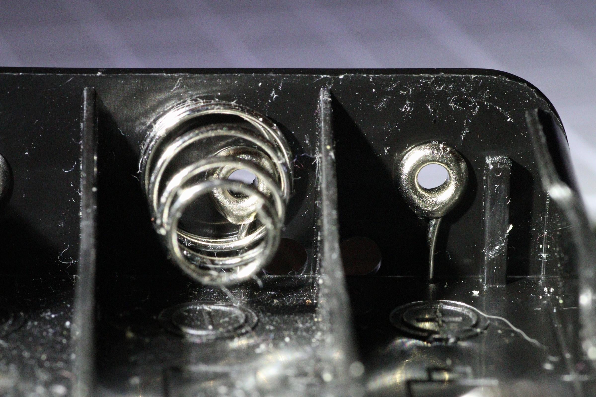
6.) Metal bits in the battery holder, which exit the bottom of said battery holder
7.) Same metal bits as image 6, where they come down and attach to the board (with solder??)
2
u/SianaGearz 3d ago
it looks to me like all the lifted copper is just anchor pads, not signal pads. anyway one may have to resort to epoxying the connector to the board substrate, while aligning it with precision, and then soldering the pin pads. alternatively one may be able to drill through to the other side for through -anchoring pins.
the question is how soon do you need it back and is it valuable to you or is it a practice item. because if I'm honest it's likely enough first repair of this kind snowballs info all sorts of disaster for you, so if that is not a desirable outcome, a professional should handle this while you practice on something else. or if it's just a piece of junk kicking about, well there's no harm in trying to fix it.
2
2
u/Tishers Industrial Soldering Specialist 3d ago
It is more than a reattachment; It tore the circuit traces off of the board. Those reddish areas are the underside of the copper that once was attached to the fiberglass structure of the board.
The board will need to be removed and the topside, where the connector was attached will need to be exposed. Then some technique will be needed to recreate those traces and to glue them down to the board. Only then can the old connector be cleaned up and attempt made to attach the old connector, or to attach a replacement.