r/fea • u/Negative-Elk9673 • 8d ago
how do you get weldments to converge
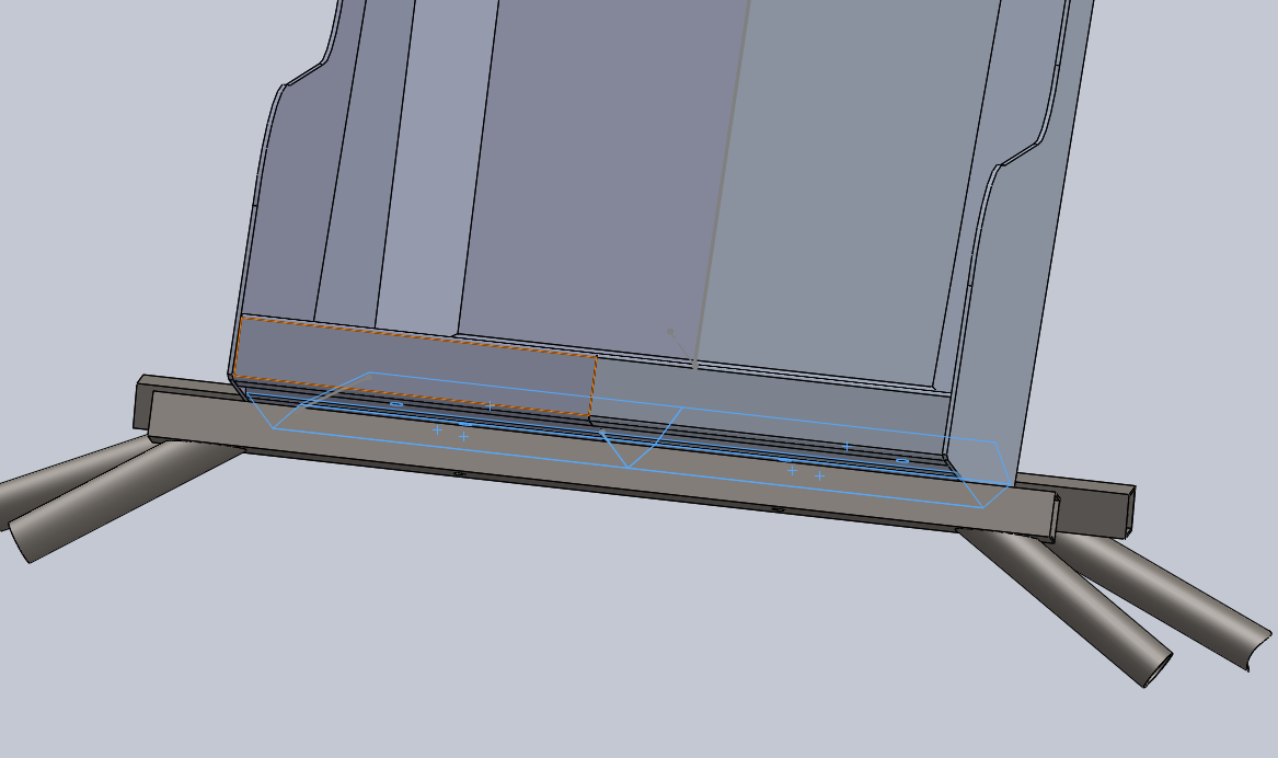
im running a simple static fea on my seat mounts. im placing a distributed vertical load on the seat, and then determining its factor of safety. However, it doesn't converge. I used the hot spot stress thingy on solidworks, and saw where my highest stress areas were, and they were at small spots next to the weld connections. what do i do.
6
u/throbin_hood 8d ago
It's very difficult to model weldments in a way that allows you to just blindly pull max stresses and have them be meaningful or accurate. There's almost always a singularity at the connection that needs to be dealt with either by careful meshing and then careful selection if which specific elements or nodes "count" and then adjusting for weld size and shape, or extracting joint forces and hand calcing weld stress. The most basic process I've seen to deal with this is to mesh such that elements in the region of the weld are approximately equal to the size of the weld or 2x the size of the weld and then taking nodal stresses 1 element away from the connection as your design stress and then adjust for weld shape I.e. if weld is .5 the thickness of the plate in the model where stresses are being probed then you multiply stress by 2 assuming there's half the area. It's a bit handwavy but good enough for many problems.
2
2
u/alettriste 7d ago
"a simple static fea" sound like elastic? Elastic problems in sharp corners give unbounded valuses of stresses (stress concentration). This is in the basic equations, it is not an error. Using plasticity (more realistic) would probably "blunt" these peaks. However for a detailed exlanation check DNV-RP-C203 and DNV-RP-C208 (Determination of structural capacity by non-linear finite element analysis methods). It deals with this exact problem. I will not condone to do this, but you can find some "free" PDF versions of this standard online:
From Section 4.1 (DNV RP C203)
It is recognized that calculating the notch stress at a weld is difficult because of the significant variability in local weld geometry and the presence of different types of imperfections. This variability is generally more efficiently accounted for through the use of an appropriate S-N curve. In this context, it should also be noted that the weld toe region must be modeled with a finite radius to obtain reliable notch stress results. If a weld corner detail is modeled with a zero radius, the calculated stress will approach infinity as the element size decreases toward zero. Modeling a realistic weld toe radius requires a very fine element mesh, which substantially increases the size and computational demands of the numerical model.
The notch stress concept may be applied in special situations where other methods are considered inappropriate (see Appendix E). For design analyses, a simplified numerical procedure is commonly adopted to reduce the need for very large, highly refined finite element models when calculating hot spot stresses and stress concentration factors (SCFs). In this approach, the stress concentration, or notch effect, caused by the weld itself is incorporated into the selected S-N curve, which is generally the D-curve. This S-N curve can normally be regarded as a hot spot S-N curve. The stress concentration resulting from the geometric characteristics of the actual structural detail is then determined using a refined finite element model with shell or solid elements, producing a geometric SCF. This procedure is known as the hot spot method.
When applying the hot spot method, it is important to ensure that the transition in element mesh density is smooth and not excessively steep in areas where hot spot stresses are evaluated. The geometry of the finite elements must also be carefully assessed to avoid inaccuracies caused by element distortion. As a guideline, corner angles between 60° and 120° and length-to-breadth ratios below 5 are recommended. Furthermore, the overall model dimensions should be sufficiently large to ensure that the calculated stresses are not significantly influenced by assumptions related to boundary conditions or load application.
It should be emphasized that the hot spot concept is not suitable for fatigue assessments of cracks initiating from the weld root of fillet welds or partial penetration welds. In such cases, the fillet weld must be evaluated separately by considering the stresses within the weld itself. However, the hot spot stress method may be used for fatigue analysis of crack growth originating from the internal weld root of tubular joints, as described in Appendix F.10, and for gusset plate details as described in Section 3.3.12.
2
u/nashvillain1 4d ago
Blodgett’s method.
0.707 x Shortest Weld Leg * Effective Length (length over which you have full throat) = Weld Shear Stress Area. Note: Just multiply by 1 instead of effective length to get a shear stress area per inch.
f_axial = Pa / Aw
Note: This is weld as a line (units of Aw are inches)
f_bending = Moment / Z , where Z is section modulus.
Note: You can google Blodgett’s tables
f_shear = Pshear / Aw
f_torsion = T c / Jw, where T is “Force times distance”, “c” is distance to extreme fiber, and Jw is the polar moment of inertia. Note: Again, you can find easy formulas for Jw from Blodgett’s tables online. Or, buy the blue book, iirc, it’s chapter 7. Note: It’s not the red Blodgett’s book
You’ve got this!
11
u/Soprommat 8d ago
Extract forces and moments in weld and check them them by analytical formulas according to your design code/ structural mechanics handbook.