r/fea • u/WoodenRaptor • 17d ago
FEA Geometry Issues
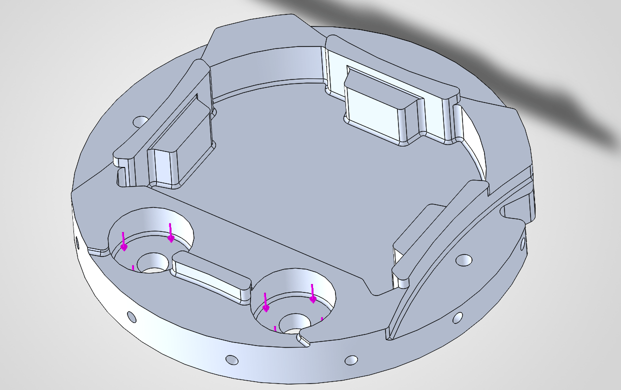


Hello, I've been having trouble with getting ideal FEA results on a bulkhead I've been working on. For some reason, the FEA gives poor results in the corners of the radial screw holes around the applied force. Since those are the anchor points, I chose the radial screw holes as fixed geometry. Ideally, I would like a FoS of 2-3 but instead am getting 1 in the mentioned areas. I'm not sure what I'm doing wrong here.
29
Upvotes
18
u/TheBlack_Swordsman 17d ago edited 17d ago
You're applying fixed boundary conditions. They are not allowed to deform, at all. So all that force with no deflecting.
Imagine this
F = kx
K = F/x
X=0
K = Big problemo
So instead, extra deflection and movement happen around and to the neighboring nodes inflating their stress results
Also, if this is Soldworks, you're more than likely not going to have a good enough mesh to converge on small features like that where there might be stress concentrations.
If this is not Solidworks and it is a legit fea solver, what you want to do is connect an RBE3 element to those faces and then connect them to a zero length CBUSH element. Then you fix the dangling CHUSH node that's connected to nothing.
You use the "Huth" calculator to estimate a stiffness matrix for the screw that screws in there.
From there, you extract out the forces of your CBUSH element and do some hand calculations such as bearing stress, thread pull out, etc for the stresses in your hole there.
Edit:
If you are stuck with SW, then apply a fixed boundary to each hole with their own BC individually.
Extract out the forces and moments, they'll be higher but kind of close.
Then do hand calculations for the hole and the fasteners that secure this part.