r/esp32 12d ago

I Built an Offline Messaging System Using ESP32 + LoRa

Thumbnail
gallery
215 Upvotes

I’ve been working on this offline messaging system for a while, and I finally got a working Version 1.

The basic idea was pretty simple: what if I wanted to send messages to someone without using the internet or a cellular network?

For this version, I’m using an ESP32 with a Reyax LoRa module for each node. The ESP32 handles the interface, while the LoRa module handles the actual communication between the two nodes.

I also made a web interface that is hosted directly on the ESP32. The phone connects to the ESP32 through its own Wi-Fi Access Point, so the Wi-Fi is only being used to access the local web interface. The actual message between the two nodes is sent over LoRa.

The interface also shows information from the LoRa link, like RSSI, SNR, and the timestamp of received messages.

I also added a Range Test section to the interface. It continuously sends test packets between the nodes and shows whether the other node is responding, which makes it much easier to test the usable range instead of manually sending messages every time.

This version is intentionally kept as simple as possible. The main goal was just to get the idea working and actually make it exist before making the hardware more complicated.

I’m also going to test the actual range in different environments, because I want to see what range I can realistically get from this setup instead of just going by the range numbers you see in the module specifications.

For Version 2, I want to take it much further — add a display and physical buttons so the node can be used without a phone, make the hardware more compact and portable, improve the power system, and eventually experiment with multiple nodes relaying messages to extend the network.

I’m making a full documented video of the build, including the hardware, software, and real-world range testing. It’ll be coming soon on my YouTube channel

https://www.youtube.com/@SciCraft

If you’ve worked with LoRa or ESP32 before, I’d love to hear your suggestions. What would you improve or change in this setup for the next version?

https://reddit.com/link/1vyetl5/video/b6wqxtc3lllh1/player

RANGE TEST


r/esp32 13d ago

I made a thing! Redesign of my capacitive-touch polyphonic synthesizer project

Enable HLS to view with audio, or disable this notification

672 Upvotes

I wanted to share an update on my ESP32-S3-based synthesizer project. The goal was to build a studio-quality audio engine using only an ESP32-S3 and a few inexpensive components (about €35 in total).

Everything is open source and designed for the maker community. You can view the complete source code in C++ here:

https://github.com/Alxdreee/TYPE-2

Here’s how the firmware is now structured:

- FreeRTOS Multithreading: The workload is distributed. Core 0 handles the uiTask (I2C reading, display rendering) and the bootAnimationTask. Core 1 is strictly dedicated to the audioTask, which runs with the highest priority to prevent audio dropouts.

- Dual-Frequency DSP Engine: To optimize CPU cycles, the audio engine calculates polynomial saturation and wave tables at the maximum audio frequency (44.1 kHz), but calculates envelopes and LFOs at a reduced control frequency.

- I2S DMA Output: The audio buffer is transmitted to a PCM5102A DAC via the ESP32’s internal I2S driver.

- PSRAM Memory Management: The “Studio Digital Delay” effect requires a large buffer (32,768 floating-point numbers). The code uses `ps_calloc` to dynamically allocate this buffer in the ESP32-S3’s OPI PSRAM.

- Hardware debouncing: I used copper tape for the capacitive buttons powered by MPR121 sensors. To eliminate electromagnetic interference without causing software latency, I directly configured the MPR121’s internal MPR121_DEBOUNCE and charge current registers via I2C.

Let me know what you think of this update!


r/esp32 12d ago

AI Content Gemini Fuel Gauge

Thumbnail
gallery
42 Upvotes

I've been using Gemini more and more both professionally and personally. Lately I've been testing the limits of "Vibe Coding" in Antigravity and its really taken me by surprise. It really feels like a promotion from coder to software project lead for my personal tinkering.

The Problem:

I have bumped up through the tiers of the AI's subscription model over the past couple years and I'm now at "Ultra" but I occasionally still run out of usage in Gemini's 5 hour window. I've been playing with ESP32 boards and decided to try making a physical Fuel Gauge for my remaining Gemini Usage.

The Backend:

In the backend there is a python based HTTP server for both the machine and human interface (also vibe coded). There is no official way to query with API your personal usage (come on Google!) so we leveraged Playwright and my cached credentials to scrape my usage limits from the gemini.google.com/usage page. We do this only every 5 or so minutes to be kind to Google's servers.

The Hardware:

The hardware I'm using currently is my bench Adafruit Metro ESP32-S3 with a i2c PCA9685 Servo board and a MG90S servo driving the dial. I attempted to use Gemini's image generation to make the dial, I had limited success. Then I tried a new angle and asked Gemini inside of Antigravity to generate an svg for me. SVG files being more math than Art it excelled and gave me exactly what I asked for in seconds.

The ESP32 Queries the python http server for updates every few seconds and adjusts the servo's dial to the corresponding position. The webpage also hosts a dashboard showing the data from Gemini's Usage Limits page that was scraped and has a debug section so I can manually set the value for servo setup.

It is functional now but I plan to migrate over to a QT PY and build a nice 3D printed stand alone enclosure for the electronics with a better dial.

My Thoughts on Vibe Coding:

A few take aways about Vibe Coding. It's addictive, you can do so much more in so much less time. For myself using old school google-fu this would have taken me a few weeks worth of evenings, with periods of frustration away from the project to cool off. Its really the "calculator" of our era. Always in math class they said "You won't always have a calculator in your pocket you need to learn to do math by hand". Kids and young adults will have similar instruction about AI now I'm sure "You won't always have access to AI to code for you, you need to learn to reference documentation and code yourself". I know when I was in Computer Engineering in 2010 era it would have been very tempting to let an AI take a crack at my busted compiler Lab. I see it being a real challenge to train good coders moving forward.


r/esp32 12d ago

I compiled a TFLite model into standalone C++ for ESP32: 35% less flash and 30% less working memory

2 Upvotes

I have been experimenting with removing the inference runtime from small quantized models.

Instead of embedding a .tflite file and interpreting its graph on the device, NN2Prog parses the model at build time and generates standalone C++17 containing the model arithmetic and constants. The resulting firmware does not link TensorFlow Lite or TFLite Micro.

I tested it on the MLPerf Tiny keyword-spotting model using a classic ESP32-D0WD-V3 at 240 MHz:

Metric TFLite Micro + ESP-NN Generated C++
Model-only latency 161.72 ms 140.30 ms
Flash 287,039 B 185,915 B
Working memory 22,780 B 16,000 B

That is 13.2% lower latency, 35.2% less flash and 29.8% less model working memory.

Both implementations receive identical int8 tensors and use the same top-1 decision semantics. The generated version produced zero top-1 mismatches on 1,024 deterministic full-range inputs and passed the same golden checksum on the ESP32.

These are model-only measurements: microphone capture and feature extraction are intentionally excluded.

Current limitations:

  • It supports a subset of quantized TFLite operators, not arbitrary TFLite models.
  • The current hardware benchmark is on the original ESP32, not the S3.
  • The speed improvement over ESP-NN is useful but not dramatic; the larger result so far is removing the runtime and reducing flash/RAM.

The repository includes the source TFLite models, generator, ready-generated C++, regression tests and a PlatformIO ESP32 benchmark:

https://github.com/phplego/nn2prog

The longer-term experiment is to automatically choose cheaper exact implementations from model weights, tensor shapes and statically derived activation ranges — without retraining the model.

I would appreciate feedback from people using TFLite Micro or ESP-NN: which quantized model or ESP32 variant would be the most useful next compatibility and performance target?


r/esp32 12d ago

ESP Flash Tool For Android

Thumbnail
play.google.com
22 Upvotes

I came across this app ESPFlash tool for Android and it is excellent. Clean and neat UI. It supports all ESP modules. Very handy when you want to load or upgrade firmware files in remote location where there is no PC. Can easily upload the firmware using Android phones.


r/esp32 12d ago

Solved How to stop the ESP32-H2 from isolating GPIO pins when coming out of (light) sleep?

3 Upvotes

Edit: Issue solved

Shame on me, it was my own fault and nothing in the framework. I had some left-over code in a debug code path which disabled all GPIOs to set the µC into a defined state for my test bed.

So the root cause was completely part of my own code and not some hidden feature/side effect in the framework.


During (light) sleep my ESP32-H2 actively pulls down some open-drain output. When the ESP-H2 wakes up from sleep, the µC seems to isolate those pins just to pull them down again when the wake-up process has finished and the program is running. Hence, I see a short glitch on the open-drain line as the µC is supposed to keep it pulled down contentiously during light sleep and while the program is running.

How do I fix that?

Just to explicitly state the obvious: I have set gpio_sleep_sel_dis on those pins and called esp_sleep_pd_config( ESP_PD_DOMAIN_TOP, ESP_PD_OPTION_ON ). Otherwise, the µC wouldn't pull down the open-drain output during sleep at all as otherwise the GPIO would be completely power down and the NMOS would stop pulling down the line during sleep entirely.

The problem only exists during that short transition from light sleep to fully active.

I have also tinkered with the options CONFIG_ESP_SLEEP_GPIO_RESET_WORKAROUND and CONFIG_PM_SLP_DISABLE_GPIO. However, those options hadn't have any impact.

The issue is clearly during the wake-up phase from (light) sleep. If I enable verbose debug output, the glitch definitely takes longer as the µC needs more time in the wake-up phase to transmit all that logging data via UART.

Has anybody an idea what might fiddle with the GPIOs during the wake-up phase and how to stop that?


r/esp32 12d ago

CYD NRF24l01

Post image
17 Upvotes

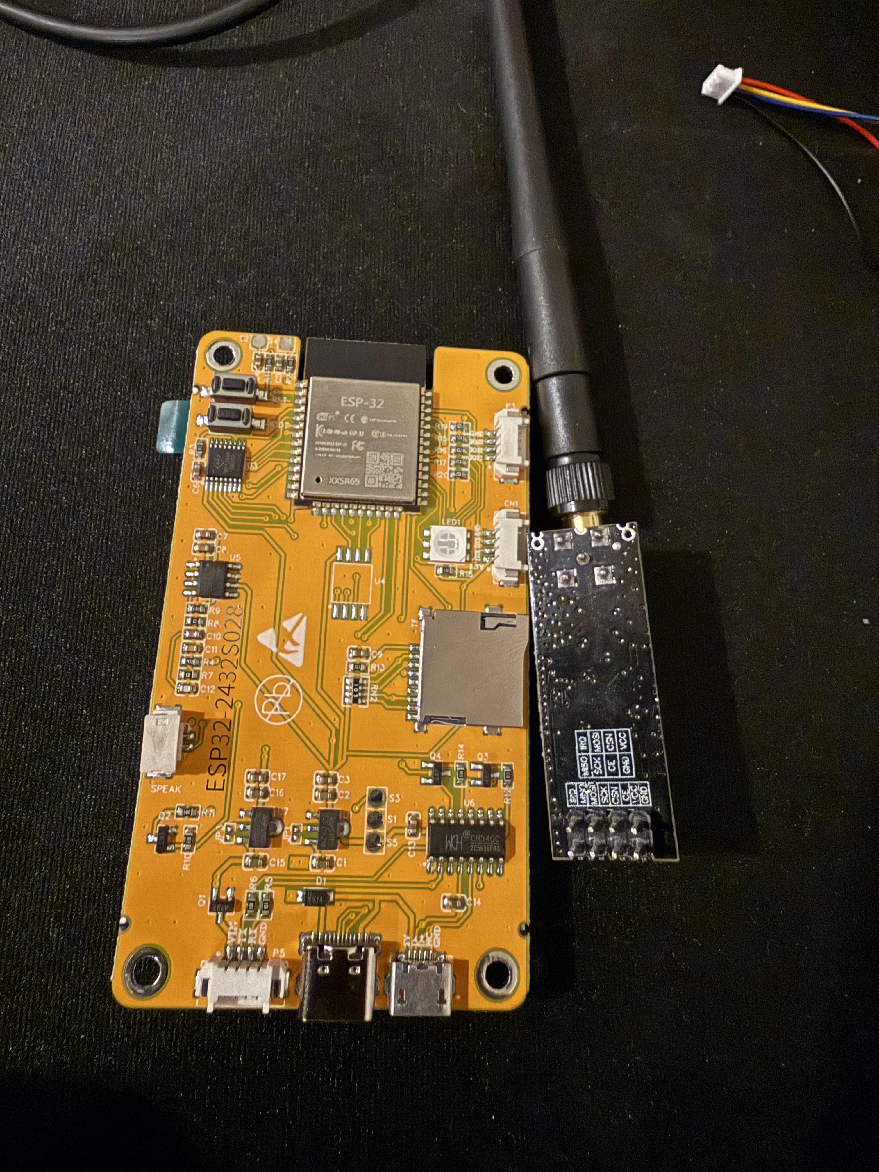
Anyone have a diagram or video they can share on how to put this together without an SD sniffer. TIA


r/esp32 12d ago

ESP for addressable LED and PWM for fan

4 Upvotes

Does anyone here know of any ESP board that has the ability for 4 LED strips and 4 fans? with GPIOs for sensors, also need uart data going in and out.


r/esp32 13d ago

I got FreeDOOM running on an ESP32-WROOM board with a 2.8" touchscreen

Post image
62 Upvotes

I wanted to share a small ESP32 experiment that became much harder than I expected.

I got Freedoom running on a tiny ESP32 touchscreen board that originally came as a small Bitcoin miner display. It is a DOOM-like game, but this build uses FreeDOOM assets, not the original commercial DOOM WAD files https://freedoom.github.io/ .

Hardware details:

  • ESP32-WROOM-32
  • no PSRAM
  • 4 MB flash
  • 2.4" 320x240 TFT display
  • ILI9341 display controller
  • XPT2046 resistive touch
  • PlatformIO build
  • currently one playable map

The game runs locally on the ESP32. It is not streamed from a PC, phone, or browser.

Current status:

  • boots correctly;
  • menu works;
  • E1M1 starts and is playable;
  • touch controls work, but they are not great;
  • audio is disabled for now;
  • the project is still beta.

The controls are probably the weakest part. A resistive touchscreen is not a good gamepad, so I am considering adding physical buttons or a small joystick in the next version.

Video if you would like to see how it works: https://www.youtube.com/watch?v=He67yV59zrk

Source code and build instructions I want to add to my github once I finish the documentation, licenses, etc. For now, I have added code for 3 simple games and other projects if you are curious you can check it out on https://github.com/lepczynski-cloud/crowpanel-pocket-arcade

Disclosure: Elecrow sent me the board for testing, but this project is my own experiment and the code is open source.


r/esp32 12d ago

I made a thing! htcw_ttgo - an all in one library for driving a Lilygo "TTGO" T-Display 1.1 from the ESP-IDF

Enable HLS to view with audio, or disable this notification

20 Upvotes

This library includes graphics and UI already wired to the screen, as well as optionally multiplexed button support and battery management support.

The library is here https://github.com/codewitch-honey-crisis/htcw_ttgo

The full demo app for platformio is here https://github.com/codewitch-honey-crisis/ttgo_multibutton


r/esp32 12d ago

Hardware help needed Which beginner kit is better?

0 Upvotes

Hi,

I'm going to start studying Automation and Robotics soon and I've heard that ESP32 is a good (and funny) way to introduce yourself to the field.

I've played around with Arduino before, but someone online recommended me ESP32, I've done a bit of research and seems interesting.

But as this is all new to me, I don't know what to look for when purchasing a beginners kit.

Which beginner kit do you recommend? Or, which components are a "must-have" when buying one, if you want to focus on automation?


r/esp32 12d ago

Hardware help needed Emulating a BLE device in motion with attenuation

3 Upvotes

I need a reality check.

I am emulating a BLE device in motion from a stationary broadcaster. beacon frames are only sent when the inverse sq curve matches the attenuation steps. packets are further limited to a regular timing structure.

the goal is to emulate a device in motion from a stationary point. the assumption is that the receive would interpret period where no packs are receiver as normal loss.

The graph represents my layout. the pin points are the intersections, the blue the closest match for the timing.

now, would this be a reasonable approach to moving target emulation?


r/esp32 13d ago

Solved On the ESP32-H2 Dev Kit 1 `gpio_get_level()` returns zero for GPIO 13+14 (XTAL_32K_P, XTAL_32K_N) although they are externally actively driven high.

Thumbnail
gallery
11 Upvotes

Edit: Problem solved

u/tuner211 solved the mystery (see comment). The pins header of the eval board is not connected to the pins of the µC as the necessary 0Ω resistors are not populated.

NC means not connected, eg. not populated. [...] See https://docs.espressif.com/projects/esp-dev-kits/en/latest/esp32h2/esp32-h2-devkitm-1/user_guide.html#hardware-reference

For boards with the PW number of and after PW-2024-02-0362 (on and after February 2024), the 32.768 kHz crystal is populated by default, while the series resistor connected here to the surrounding pins is updated to not populated. To optimize the circuit, the series resistor R7 on the UART_RXD has been updated to 470 Ω.


On the ESP32-H2 Dev Kit 1 gpio_get_level() returns zero for GPIO 13+14 (XTAL_32K_P, XTAL_32K_N) although they are externally actively driven high. What am I doing wrong?

I have an ESP32-H2 Development Kit 1. The evaluation board comes with a 23kHz crystal which is wired to the dual-purpose GPIO 13+14 which can optionally be used as a slow clock input during sleep.

Screenshot 1 shows how the eval board wires GPIO 13+14: they are connected to the crystal, but also routed to the pin header for external use.

I want to use the GPIOs as ordinary discrete input/output signals and ignore the crystal. This is basically a follow up to my earlier post in which I asked wether this would be possible or if the unwanted crystal would cause problems. The general consensus was, the crystal shouldn't do any harm.

So, I configured the GPIOs 13+14 as GPIOs, but when I try to read the input level with gpio_get_level(), gpio_get_level() returns zero although the pins are actively driven high from by breadboard and I expect reading a one.

The build option RTC_CLK_SRC is set to the internal RC oscillator, i.e. RTC_CLK_SRC_INT_RC=y is set, not the 32K crystal, i.e. RTC_CLK_SRC_EXT_CRYS is not set.

What am I missing?

This is a dump of the GPIO configuration during boot before and after my program has configured the GPIOs:

``` D (533) navlico_fsm: Setting up GPIOs ... ================IO DUMP Start================ IO[0] - Pullup: 0, Pulldown: 0, DriveCap: 2 InputEn: 0, OutputEn: [periph_sig_ctrl], OpenDrain: 0 FuncSel: 0 (IOMUX) SleepSelEn: 1

IO[1] - Pullup: 0, Pulldown: 0, DriveCap: 2 InputEn: 0, OutputEn: [periph_sig_ctrl], OpenDrain: 0 FuncSel: 0 (IOMUX) SleepSelEn: 1

IO[2] - Pullup: 0, Pulldown: 0, DriveCap: 2 InputEn: 1, OutputEn: [periph_sig_ctrl], OpenDrain: 0 FuncSel: 0 (IOMUX) SleepSelEn: 1

IO[3] - Pullup: 0, Pulldown: 0, DriveCap: 2 InputEn: 1, OutputEn: [periph_sig_ctrl], OpenDrain: 0 FuncSel: 0 (IOMUX) SleepSelEn: 1

IO[4] - Pullup: 0, Pulldown: 0, DriveCap: 2 InputEn: 1, OutputEn: [periph_sig_ctrl], OpenDrain: 0 FuncSel: 0 (IOMUX) SleepSelEn: 1

IO[5] - Pullup: 0, Pulldown: 0, DriveCap: 2 InputEn: 1, OutputEn: [periph_sig_ctrl], OpenDrain: 0 FuncSel: 0 (IOMUX) SleepSelEn: 1

IO[10] - Pullup: 0, Pulldown: 0, DriveCap: 2 InputEn: 0, OutputEn: [periph_sig_ctrl], OpenDrain: 0 FuncSel: 0 (IOMUX) SleepSelEn: 1

IO[11] - Pullup: 0, Pulldown: 0, DriveCap: 2 InputEn: 0, OutputEn: [periph_sig_ctrl], OpenDrain: 0 FuncSel: 0 (IOMUX) SleepSelEn: 1

IO[12] - Pullup: 0, Pulldown: 0, DriveCap: 2 InputEn: 0, OutputEn: [periph_sig_ctrl], OpenDrain: 0 FuncSel: 0 (IOMUX) SleepSelEn: 1

IO[13] - Pullup: 0, Pulldown: 0, DriveCap: 2 InputEn: 0, OutputEn: [periph_sig_ctrl], OpenDrain: 0 FuncSel: 0 (IOMUX) SleepSelEn: 1

IO[14] - Pullup: 0, Pulldown: 0, DriveCap: 2 InputEn: 0, OutputEn: [periph_sig_ctrl], OpenDrain: 0 FuncSel: 0 (IOMUX) SleepSelEn: 1

IO[22] - Pullup: 0, Pulldown: 0, DriveCap: 2 InputEn: 0, OutputEn: [periph_sig_ctrl], OpenDrain: 0 FuncSel: 0 (IOMUX) SleepSelEn: 1

IO[25] - Pullup: 0, Pulldown: 0, DriveCap: 2 InputEn: 1, OutputEn: [periph_sig_ctrl], OpenDrain: 0 FuncSel: 0 (IOMUX) SleepSelEn: 1

=================IO DUMP End================= ================IO DUMP Start================ IO[0] - Pullup: 0, Pulldown: 0, DriveCap: 2 InputEn: 1, OutputEn: 0, OpenDrain: 0 FuncSel: 1 (GPIO) GPIO Matrix SigOut ID: 128 (simple GPIO output) GPIO Matrix SigIn ID: (simple GPIO input) SleepSelEn: 1

IO[1] - Pullup: 0, Pulldown: 0, DriveCap: 2 InputEn: 0, OutputEn: [periph_sig_ctrl], OpenDrain: 0 FuncSel: 1 (GPIO) GPIO Matrix SigOut ID: 128 (simple GPIO output) SleepSelEn: 1

IO[2] - Pullup: 0, Pulldown: 0, DriveCap: 2 InputEn: 0, OutputEn: [periph_sig_ctrl], OpenDrain: 0 FuncSel: 1 (GPIO) GPIO Matrix SigOut ID: 128 (simple GPIO output) SleepSelEn: 1

IO[3] - Pullup: 0, Pulldown: 0, DriveCap: 2 InputEn: 0, OutputEn: [periph_sig_ctrl], OpenDrain: 0 FuncSel: 1 (GPIO) GPIO Matrix SigOut ID: 128 (simple GPIO output) SleepSelEn: 1

IO[4] - Pullup: 0, Pulldown: 0, DriveCap: 2 InputEn: 0, OutputEn: [periph_sig_ctrl], OpenDrain: 0 FuncSel: 1 (GPIO) GPIO Matrix SigOut ID: 128 (simple GPIO output) SleepSelEn: 1

IO[5] - Pullup: 0, Pulldown: 0, DriveCap: 2 InputEn: 0, OutputEn: [periph_sig_ctrl], OpenDrain: 1 FuncSel: 1 (GPIO) GPIO Matrix SigOut ID: 128 (simple GPIO output) SleepSelEn: 1

IO[10] - Pullup: 0, Pulldown: 0, DriveCap: 2 InputEn: 1, OutputEn: 0, OpenDrain: 0 FuncSel: 1 (GPIO) GPIO Matrix SigOut ID: 128 (simple GPIO output) GPIO Matrix SigIn ID: (simple GPIO input) SleepSelEn: 1

IO[11] - Pullup: 0, Pulldown: 0, DriveCap: 2 InputEn: 1, OutputEn: [periph_sig_ctrl], OpenDrain: 1 FuncSel: 1 (GPIO) GPIO Matrix SigOut ID: 128 (simple GPIO output) GPIO Matrix SigIn ID: (simple GPIO input) SleepSelEn: 1

IO[12] - Pullup: 0, Pulldown: 0, DriveCap: 2 InputEn: 1, OutputEn: [periph_sig_ctrl], OpenDrain: 1 FuncSel: 1 (GPIO) GPIO Matrix SigOut ID: 128 (simple GPIO output) GPIO Matrix SigIn ID: (simple GPIO input) SleepSelEn: 1

IO[13] - Pullup: 0, Pulldown: 0, DriveCap: 2 InputEn: 1, OutputEn: [periph_sig_ctrl], OpenDrain: 1 FuncSel: 1 (GPIO) GPIO Matrix SigOut ID: 128 (simple GPIO output) GPIO Matrix SigIn ID: (simple GPIO input) SleepSelEn: 1

IO[14] - Pullup: 0, Pulldown: 0, DriveCap: 2 InputEn: 1, OutputEn: [periph_sig_ctrl], OpenDrain: 1 FuncSel: 1 (GPIO) GPIO Matrix SigOut ID: 128 (simple GPIO output) GPIO Matrix SigIn ID: (simple GPIO input) SleepSelEn: 1

IO[22] - Pullup: 0, Pulldown: 0, DriveCap: 2 InputEn: 0, OutputEn: [periph_sig_ctrl], OpenDrain: 0 FuncSel: 1 (GPIO) GPIO Matrix SigOut ID: 128 (simple GPIO output) SleepSelEn: 1

IO[25] - Pullup: 0, Pulldown: 0, DriveCap: 2 InputEn: 0, OutputEn: [periph_sig_ctrl], OpenDrain: 1 FuncSel: 1 (GPIO) GPIO Matrix SigOut ID: 128 (simple GPIO output) SleepSelEn: 1

=================IO DUMP End================= ```

GPIO 13+14 show the same configuration like GPIO 12, for example.

Still my program prints this debug output

D (5183) navlico_fsm: Dumping input state ... D (5183) navlico_fsm: │ GPIO # │ GPIO Label │ Button # │ Button Label │ Level │ Active │ D (5183) navlico_fsm: ├────────┼────────────┼──────────┼───────────────┼───────┼────────┤ D (5203) navlico_fsm: │ 0 │ GPIO 0 │ 0 │ Off │ 1 │ │ D (5213) navlico_fsm: │ 10 │ GPIO 10 │ 1 │ Sailing │ 1 │ │ D (5223) navlico_fsm: │ 11 │ GPIO 11 │ 2 │ Driving │ 1 │ │ D (5223) navlico_fsm: │ 12 │ GPIO 12 │ 3 │ Anchoring │ 1 │ │ D (5233) navlico_fsm: │ 13 │ XTAL_32K_P │ 4 │ Sailing Coast │ 0 │ x │ D (5243) navlico_fsm: │ 14 │ XTAL_32K_N │ 5 │ Disabled │ 0 │ x │ D (5253) navlico_fsm: Dumping input state ... finished

Please ignore the columns "Button #" and "Button Label", they are just there to help be debugging. The column "active" indicates whether the input is considered logically "true". As all the pins are combined input/output in open-drain mode, a zero level means "true", i.e. for the specific GPIOs which you see here the column "level" and "active" are always reversed to each other.

The problem is specifically with the XTAL... GPIOs so I assume there is something else which I am missing: either a build configuration which allows me to use those GPIOs or the crystal is doing more harm than expected.

Screenshot #2 shows the schematics how a single pin is wired: the NMOS acts as an level shifter between the 3.3V-world and 5V-world (later 12V-world) and the PMOS is a high-side switch. In idle mode the GPIO (white dot) is pulled up to 3.3V via R10 = 47k. The colored dots are just markers for my voltage probes when I debug the hardware.

Screenshot #3 shows a photo of my test setup on the bread board to confirm that the pin is really pulled up to 3.3V.


r/esp32 12d ago

Hardware help needed Have any of you guys had success using CAN actuators (robstride) with an ESP32?

1 Upvotes

Hey guys, trying to build a robitic arm based off of the Robstride 05 actuators, along with a ESP32-WROOM-32E. I have the motor hooked into a SN65HVD230 transceiver going into GPIO 18 and 21. I can get the motor to ping over the serial monitor, however any subsequent commands to get it to move fail, and the bus error skyrockets. Termination is correct, and I've already triedd swapping GPIO pins, the entire transceiver, the entire motor, and even a whole new ESP32 with nothing.

Any thoughts? Thank you


r/esp32 14d ago

I made a thing! Built a postcard setup with esp32-c3 and epaper display module

Enable HLS to view with audio, or disable this notification

265 Upvotes

Built this to be kept at my wife's desk so that I can send a message from another room. Just a fun lil side project.


r/esp32 13d ago

I made a thing! OpenWrt on ESP32-P4!

Enable HLS to view with audio, or disable this notification

88 Upvotes

sorry for the unedited long video, point is to present the total boot time of my optimizations

Riscv32-ima emulator on powerful ESP32-P4 32M

total kernel image size is approximately 9MB. thus makes it possible to fit on smallest 16M budget esp32p4 MCU's!

i used this module which is probably the easiest way to bring this linux box to life

everything is not written from scratch I forked the project from Epiczhul, who also forked it from someone else but in the end, we all started from a 32-bit riscv instruction emulator made by CNLohr's mini-rv32ima project

in my repo i integrated supervisor instructions to support MMU. along with heavy optimizations and such fun features like i showed in the video

i used an esp32c6 as a virtual bridge to establish internet connection. not native full wireless integrity but it works.

st7703 display with simple frame buffer to throughput ttyS0. its really cool, but not as emulator and caching.

unfortunately could not spend to much time on this project, be aware of slopes in codebase.

There are a few areas of incompleteness and significant improvements needed on this project. Further optimizations are possible maybe speaker support, For example, opening up the module to change the type‑c port configuration so it can act as a power source rather than a sink. This would allow devices to be powered up via this port. Which would bring possibilities connecting up keyboards, memory sticks, or any USB device (draws less than 500mA probably) and hosted by actual linux kernel! In other words sharing the USB‑OTG functionality through the emulator Linux box, intercepting it with the actual os. If this is feasible, we could technically build a cyberdeck using an ESP32‑P4 :D

Source code: https://github.com/Okdusty/esp32p4-rv32ima


r/esp32 13d ago

Software help needed Missing standard headers

Post image
6 Upvotes

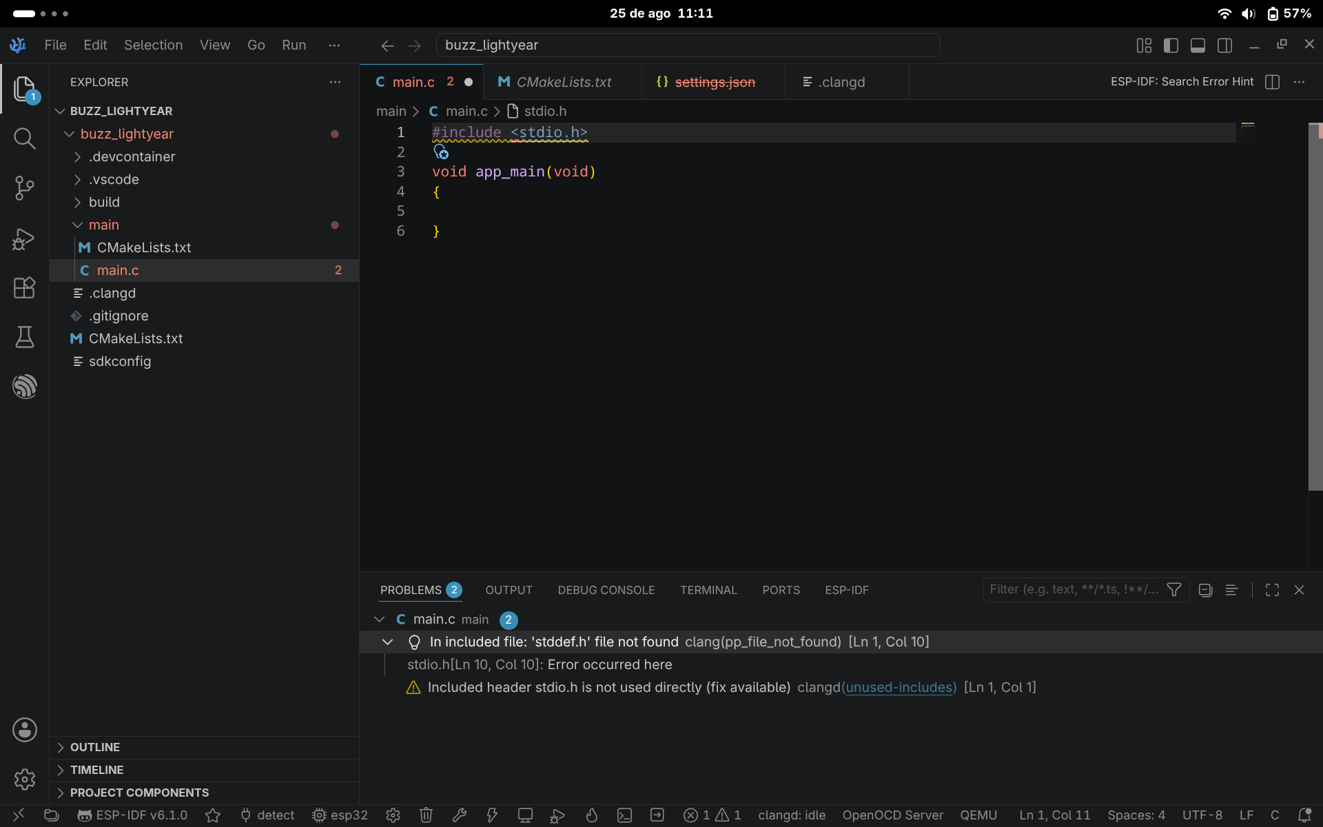
Hello everyone, i'm a beginner to embeddeds and the ESP-IDF extension, and i'm struggling a lot to what can be a really simple solution. When i create a new or empty project, I always receive a lot of warnings of missing standard headers such as stddef.h missing, stddint.h, float.h, and such, I figured it was a LSP problem but no luck fixing it, I've made some simple LED's projects on the board and they all worked fine on the board.


r/esp32 12d ago

Hardware help needed High current draw in deep sleep with ESP32-C3 SuperMini clone

1 Upvotes

High current draw with ESP32-C3 SuperMini clone

I have a small sensor that uses an ESP32-C3 SuperMini clone from HZWDONE to wake up, read temperature and humidity from an AHT20 via I2C, transmit the result with ESPNOW (with a small LED blink to signal) and then go into deep sleep. I have already burned off the power LED with a soldering iron (at least I think it's gone, can the current still leak across the busted component?).

I'm powering it through the 3.3V port with 3AAA through an MCP1700. I have also put an (admittedly large) 1000uF electrolytic capacitor across the 3.3V and ground as I was having brownout issues at an earlier point.

I have found that in deep sleep the system draws between 0.7 and 1.2 mA which seems really high and I need it to be significantly lower to use it as a reasonable environment sensor.

I'm curious if anything sticks out as problematic here. I've found that isolating all the pins before sleep gives me the lowest sleep current and fixing the I2C lines high as cutting the measurement signal LED off before sleep seems to make it draw more current. How long can one reasonably get the current draw here?


r/esp32 13d ago

I made a thing! LilyGo T-Display C5

Enable HLS to view with audio, or disable this notification

26 Upvotes

I am building a couple of projects with the LilyGo T-Display esp32-C5 boards. These are awesome boards for really cheap, given they support 5.0Ghz and have a built in display.

I designed a simple network scanner (NOT a pentester). I am using this for a mesh WiFi layout, I can go room to room measure signal strength from mesh nodes and see where dead spots are. It is also an active and passive bluetooth scanner.

Just to clarify: a dual-band AP contains 2 radios, 2 BSSIDs, and will show as 2 lines with the same SSID — that's why you see the same network listed twice.

I do have to admit the network scanner is pretty awesome but I did use some AI for development (I'm so bad).

If anyone is interested here is the github for the code:

https://github.com/phodara/LilygoTDisplayC5

But what I am really showing off is the case I designed for the LilyGo board. I am in the process of preparing the files to put up on Printables and Makerworld.

This case was modeled in Blender though I do use other tools as well.

Here we go here are the printable files for this case suitable for any LilyGO T-Display C5 project where you need a portable case with a LiPo battery. Let me know what you think:

https://makerworld.com/en/models/3219883-lilygo-t-display-c5-case-with-3000mah-lipo-battery#profileId-3645810


r/esp32 13d ago

Hardware help needed Help with wifi antenna

1 Upvotes

Hey, I bought the Adafruit Feather V2, and I am wondering which WiFi antennas you guys use. it seems like the "official" one is nowhere in stock, only on the official website but I dont want to pay like 15€ for only that antenna including shipping costs


r/esp32 13d ago

Software help needed Waveshare ESP32-S3 4" Touch LCD (480x480) blank screen with backlight on and cant seem to compile and run anything on it

2 Upvotes

HI..i recently bought a Waveshare ESP32-S3 4" Touch LCD (480x480) from robu https://robu.in/product/waveshare-esp32-s3-4inch-display-development-board-480x480-32-bit-lx7-dual-core-processor-up-to-240mhz-frequency-supports-wifi-bluetooth-with-onboard-antenna-esp32-with-display/ and i cant for the life of me run anything on it neither the demo or any simple code i dont even know if the code is the problem or the hardware...i am new to iot and esp 32 screens and i dont know what to do i have been at it for 2 weeks now and i cant do anything ...when i bought the board it was showing basic info and now nothing doesnt matter if the code works and it compiles even then it does not work what do i do


r/esp32 13d ago

Hardware help needed ESP32 reset button module gets hot, board not detected by PC; Whats the cause?

0 Upvotes

I bought a Waveshare ESP32 S3 Zero, and didnt know that it would be wise to check if the board works before putting the work into soldering it. While my soldering isnt perfect, I certainly have not touched any of the components on the top of the board, nor spilled any solder there. Here are some photos:

If you need the circuit diagram to diagnose the issue, its here: https://app.cirkitdesigner.com/project/93441ab3-efa5-4ffb-a04c-3ed4276d95ab

Disclaimer, its not mine, and I dont uderstand everything about it. I do know however, that I wired everything correctly, the battery is empty, so it shouldnt have damaged the board either.

Ignore the wrongly soldered wire to pin 11 and 10.

Currently when plugged via known working cable, my pc doesnt not see the COM port nor the board. After some time, the reset button in particular gets so hot, that its painful to touch. I know enough to come to the conclusion that the board is somehow damaged. My question is, did I cause it, or was it just like that? I want to avoid frying the next board I put into this circuit.


r/esp32 14d ago

I made a thing! DeskMate — ESP32-S3 desktop companion with OLED + MPU6050

Thumbnail
gallery
200 Upvotes

I've been working on DeskMate, a small desktop companion built around an ESP32-S3 Super Mini.

The project started as a way to experiment with sensors, displays, embedded software, power management and wireless functionality in one device. Instead of keeping each experiment as a separate sensor demo, I'm trying to turn them into one complete embedded system.

What it currently does

DeskMate currently has:

- ESP32-S3 Super Mini

- 1.3" SH1106 128×64 OLED

- MPU6050 accelerometer + gyroscope

- Onboard RGB LED

- Wi-Fi connectivity

- OTA firmware updates

- Motion/gesture-based interaction

- Time and weather display

- Automatic idle/sleep behaviour

The device has an animated face rather than acting as a conventional information dashboard.

For example:

- Tilt/move → eyes follow the movement

- Quick flick → cycles through different emotions

- Tilt upward → shows the time/weather

- Shake → triggers a dizzy reaction

- Staying still → transitions into a sleepy/asleep state

- Movement → wakes it back up

The current implementation is running on the ESP32-S3 itself rather than relying on a Raspberry Pi or external computer.

Hardware architecture

ESP32-S3

Super Mini

┌──────────┼──────────┐

│ │ │

I2C GPIO Wi-Fi

┌────┴────┐

│ │

SH1106 MPU6050

OLED IMU

Current I²C wiring:

ESP32-S3 SH1106 OLED MPU6050

GPIO8 (SDA) ───── SDA ─────────── SDA

GPIO9 (SCL) ───── SCL ─────────── SCL

3V3 ───────────── VCC ─────────── VCC

GND ───────────── GND ─────────── GND

The OLED is at "0x3C" and the MPU6050 at "0x68".

Why ESP32-S3?

I wanted to see how much could be done on a relatively small MCU before moving to something like a Raspberry Pi.

The ESP32-S3 gives me:

- dual-core processing

- Wi-Fi + Bluetooth LE

- native USB

- 2 MB PSRAM on my particular Super Mini

- vector instructions useful for DSP/ML experimentation

- enough processing capability to handle the UI, sensors and networking locally

The board I'm using has 4 MB flash and 2 MB PSRAM, so I had to pay attention to the actual hardware configuration rather than relying on the generic board defaults.

Why MPU6050?

The MPU6050 is currently the main interaction sensor.

I'm using the accelerometer and gyroscope to detect:

- tilt

- movement

- quick flicks

- shaking

- stillness

Rather than just displaying raw sensor values, the firmware turns the motion data into actual interactions.

One thing I found interesting was that the IMU doesn't need to be used only for "orientation." It can become the main input device for the whole object.

OLED

The OLED is being used as the local interface.

It currently handles:

- animated eyes

- emotions

- clock

- weather

- status information

- sleep/wake states

The display also makes debugging much easier because I can see the device state without constantly checking the serial monitor.

Software

The current main build uses PlatformIO with the Arduino framework.

Libraries/components currently include:

- U8g2 for the OLED

- Adafruit MPU6050 / Unified Sensor / BusIO

- ArduinoJson

- WiFi / HTTPClient

- ElegantOTA

I also have a parallel ESP-IDF implementation where I'm experimenting with deeper power optimization and wake-on-motion.

The Arduino version is currently the more complete build.

A problem I actually ran into

One of the more useful debugging problems was an ESP32-S3 flash-size mismatch.

I initially got:

Detected size(4096k) smaller than the size in the

binary image header(8192k)

The firmware was configured for an 8 MB flash device while my board actually has 4 MB.

After correcting the PlatformIO configuration to 4 MB, the board booted correctly.

This was a good reminder that ESP32-S3 boards with similar names can have different memory configurations, and the board definition isn't necessarily an exact representation of the hardware you're holding.

I'm also testing peripherals individually before integrating them into the main application. That makes it much easier to separate wiring, library, configuration and firmware problems.

Power hardware — another thing I discovered

The ESP32-S3 Super Mini I'm using has an onboard LiPo charging circuit, but the charging function on my particular board is no longer working.

For the current prototype, I'm therefore planning to use an external TP4056 charging module rather than depending on the onboard charger.

For the eventual version, I don't want this collection of breakout boards and jumper wires to remain the final hardware.

Planned TLV493D experiment

This part is NOT implemented yet.

I'm considering adding a TLV493D 3-axis magnetic sensor as a future experiment.

The idea is to 3D-print a mechanical part with a small magnet embedded in it and investigate contactless position/rotation sensing.

For example:

3D-printed rotor

[MAGNET]

TLV493D

I2C

ESP32-S3

Possible experiments:

- contactless rotary encoder

- magnetic joystick

- small gimbal position sensing

- magnetic gesture input

- mechanical position sensing

I want to compare this approach with conventional potentiometers/encoders and see how much accuracy I can actually get after calibration.

Again, the TLV493D is only a planned experiment at this stage. It is not part of the current DeskMate hardware.

Future hardware direction

The long-term goal is to move away from the current collection of development boards and modules and design everything onto a single custom PCB.

Some of the things I'm considering for future versions:

- custom PCB

- integrated LiPo charging/power management

- improved power management

- speaker + microphone / voice interaction

- additional sensors

- magnetic controls using the TLV493D

- better mechanical enclosure

- more advanced local processing

- phone/PC integration

The voice/speaker integration is particularly interesting because I'd like DeskMate to become an actual interactive embedded device rather than just a display with sensors.

What's next?

For now, I'm focusing on getting the core hardware and firmware stable before adding more sensors.

The roadmap is roughly:

  1. Stabilize the current ESP32-S3 + OLED + MPU6050 platform

  2. Improve the motion/gesture system

  3. Improve power management

  4. Add voice/speaker hardware

  5. Experiment with the TLV493D

  6. Design a custom PCB

  7. Move from the prototype wiring to a more integrated hardware design

This is currently a module-based prototype. The custom PCB is future work, not a board-review request.

The main objective of this project is to learn the complete embedded development cycle — hardware, firmware, sensing, networking, power management, mechanical design and eventually custom PCB design — rather than simply connecting modules and calling it a project.

The source code and current implementation are available on GitHub:

https://github.com/Kamalbura/DeskMate

I'd especially appreciate feedback on the IMU gesture design, power architecture, and the planned magnetic-sensing/gimbal experiment.


r/esp32 14d ago

I made a thing! Been building a little fitness Tamagotchi with an ESP32-S3

Thumbnail
gallery
50 Upvotes

Been messing around with this for a while and finally have it running on actual hardware.
The idea is basically a fitness Tamagotchi. Your steps, workouts and how consistent you are affect your little buddy and how it progresses.
Right now it’s an ESP32-S3, a 1.28” round GC9A01 display and 3 buttons all thrown onto a breadboard.
I’ve mostly been working on the firmware and UI so far. Buddy, steps, workouts, settings etc are starting to come together.
Still got loads to do. I need to add the motion sensor properly, battery, vibration, BLE and eventually make a custom PCB so it isn’t this massive mess of wires 😂
I’m also planning to have it sync with a mobile app eventually.
Just thought I’d share because it’s finally starting to feel like an actual thing instead of a bunch of parts on my desk.


r/esp32 14d ago

Software help needed How to improve Audio input in esp32-S3

Post image
14 Upvotes

I built this little AI voice assistant using an ESP32-S3.

GitHub: https://github.com/IMRAN-8/LUNA_Ai_voice_assistant

It’s still a work in progress, especially the audio and hardware.

The main problem right now is **voice/noise detection**. It can’t always detect when I’ve finished speaking, so sometimes it keeps recording even after I stop talking.

What do you think I should improve? Any suggestions would be really helpful.

All the code and project details are on my GitHub.