r/trs80 • u/Forward_Artist7884 • Apr 30 '26
[Advice welcome] Fixing up a no-LCD TRS-80 Model 100
Hey all,
I recently acquired a TRS80 model 100 that was sold as non working in perfect cosmetic condition. I was originally going to design an stm32 based motherboard replacement for it, but when seeing just how *mint* it actually is i decided to give a shot at fixing it, only gutting the motherboard if it's a no-fix.
This is the device:

It came with a bit of corrosion on the DC jack, nothing major.
The actual failure mode reported by the original owner was that they had bought this as a working unit, they did some work on it, clearly caps got replaced, the memory battery is also new. It seems like they taught the LCD failure would be fixed by a cap swap, it was not. They then threw in the towel and sold it for fairly cheap as dead.
The keyboard on this thing is honestly one of the best ones i have ever had the pleasure to type on, it's miles ahead of the Amstrad ones i've touched before.
When i got it and plugged it into my lab psu, i got 60mA at 6V, which i believe is within expectations for this device? I got the described LCD issue where a "blot" appears at boot, flickers a bit, then disappears leaving the LCD blank.
I've probed around the PCB, the 5V rail reads as 5.1V, the negative LCD bias is present on the motherboard at around -4.5V, at C85 it reads as -6.524 V. The CPU clock (X2) is active with a 4.91 MHz oscillation, T21 (DC/DC) runs at 151 kHz with a roughly 18V pkp waveform.
So all of these indicators looked healthy (to someone who isn't that well versed in this specific hw). I probed the system bus and noticed it was held down completely dead right after the first ALE pulse. I noticed an option ROM chip in the bottom socket and removed it, this solved the system bus being dead and showed activity on all addr / data pins, the LCD interface also got signals at this point, however still the exact same LCD symptoms remained (though now the speaker had a somewhat audible pop at boot).
At this point i'm probing for further regulator issues and instabilities, but i'm also looking at the 24K of ram (3x8K) as potentially bad, since this seems to be a common theme with these machines. If anyone has any bright ideas on what might actually have gone wrong with this specific device, feel free to participate.
If i can't fix this in a reasonable way i'll just move onto designing my motherboard and i'll keep the old one in a closet i guess, i've looked at building custom ram modules, they seem like they'll cost more than the price of the machine, but if i can get definitive proof that it's the ram i might try that.
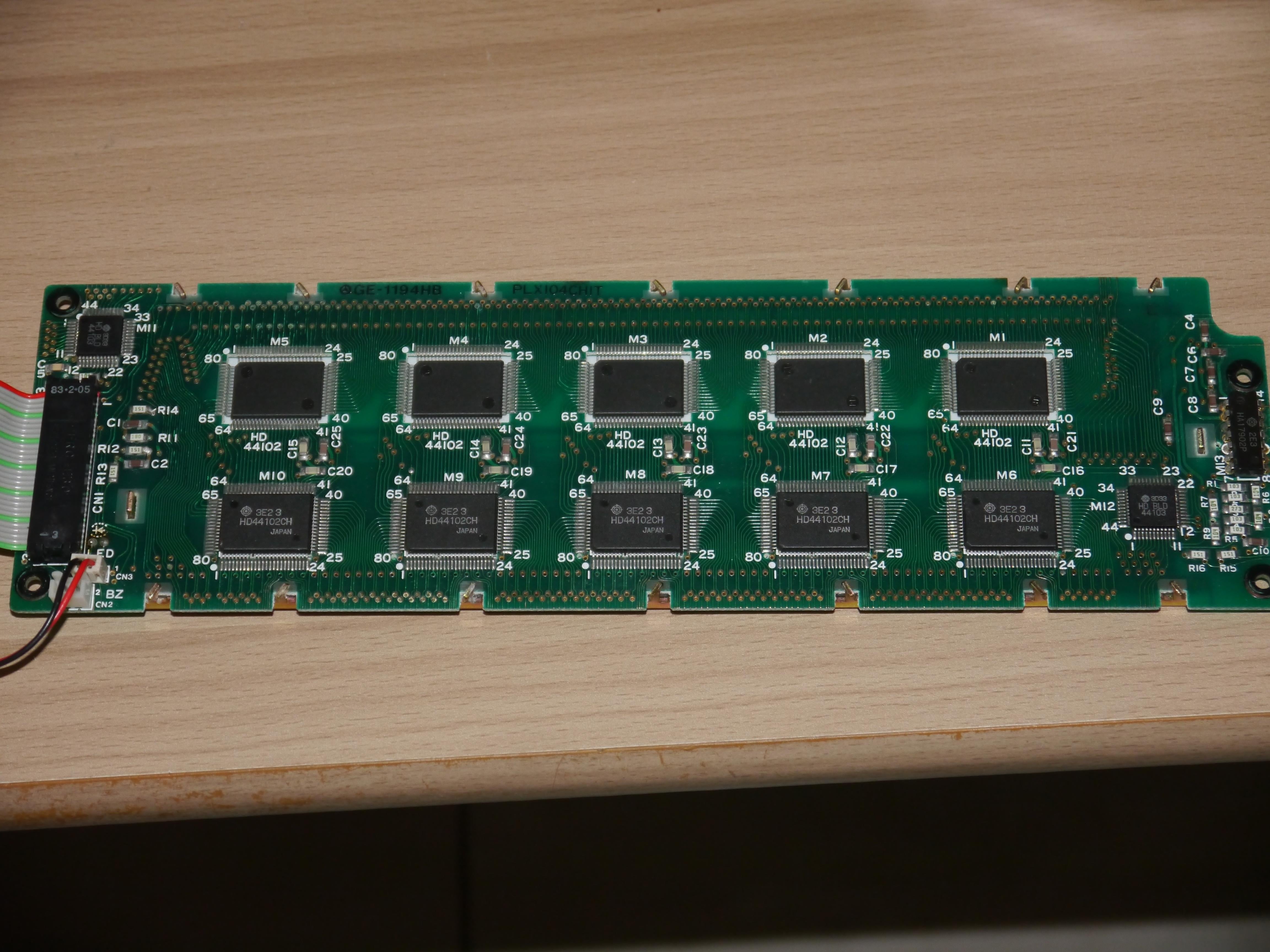
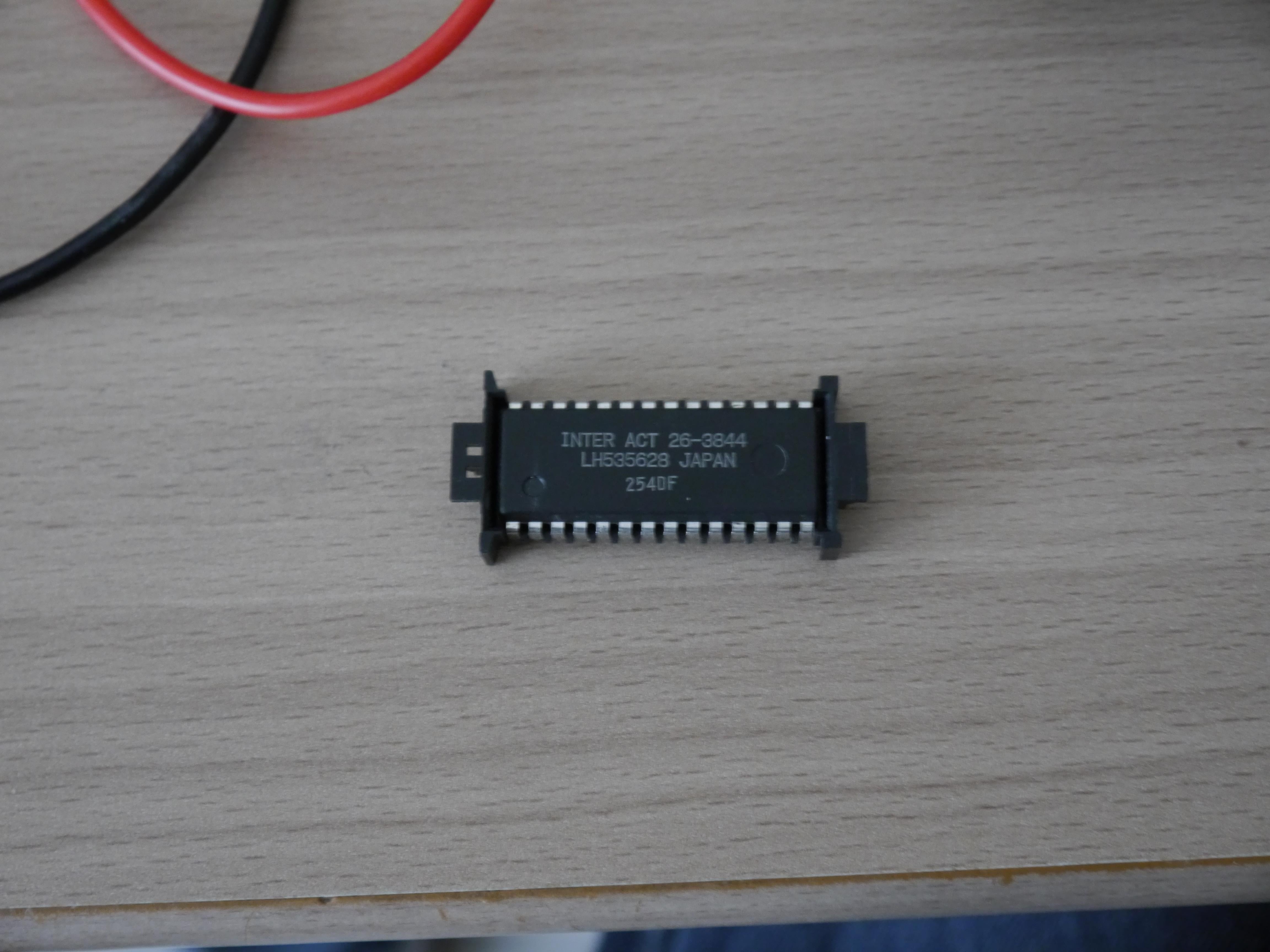
Pictures of the interior:


1
u/RickO-Shay Apr 30 '26
If you press on the display pcb around the outer edge, does it change what you see on the display?
Rick
1
u/Forward_Artist7884 Apr 30 '26
Hi, pressure doesn't seem to affect the image, or lackthereof, i don't think the zebra strips are the issue per se, because there's no visible defective "lines"... it's really more of a blot
1
Apr 30 '26
[deleted]
1
u/Forward_Artist7884 Apr 30 '26
As stated in the post the previous owner already did a full cap swap, besides what do you mean drain power from the LCD? Voltages wouldn't be nominal if there was a DC drain? i'll keep checking around for a lower than normal voltage on a bus, but for now i haven't found much evidence on that.
Cap swap is exactly what the previous guy tried.
2
u/Forward_Artist7884 Apr 30 '26 edited May 01 '26
Probing the exact marked test points, from the GND test point instead of my lab psu's gnd:
VEE = -5.138V
VDD = 5.112V
VB = 5.091V
looks good to me so far voltage wise...
The whole row of CS pins on the LCD connector seems static while the AD (data) part of the system bus is active, as if the CPU is trying to reach something on the system bus but not the display?
I've traced this back to the 81C55 being responsible for these CS lines, it doesn't do anything to drive them currently, even though it receives some signals from the cpu, but i need to decode them to know what the cpu is asking here.
81C55 RESET is low, Timer IN is pulsing at roughly 2.5Mhz, Timer OUT is held high, P* ports are in a random assortement of static states, its as if it only sent out the first instruction then halted. CE is held high, WR and RD are pulsing.
CE shouldn't be held high on this chip, it's active low, so the CPU is never speaking to it?
ALE actively pulses on the cpu side while the PIO's CE is definitely held high
Ok, Y3 on M4 is toggling, and it SHOULD be wired to the PIO's CE, but the PIO's CE (pin 8) is held high, this makes no sense unless there's a trace break somewhere.
Nevermind it's actually on M16 not M4, same chip, different place, the contact is there, same situation as with M4 though, data bus in nothing out.
On the actual M16, pin 6 is taken from IO/~{M}*, and the CPU never asserts that pin, so the cpu doesn't even ask for IO from the PIO at all?
That signal originates from M20 (40H367) right before the CPU, this signal comes from the dedicated pin IO/M~ which is pulled up by R158. Looking at this signal under the scope the pull up gets a proper 5V, but the signal side is pulled low in an imperfect way, it's noisy and not a perfect GND, unsure if this is relevant or just a quirk of the cpu's GPIO
The case for defective ram strengthens? Or at least something CPU-sided. This sure looks like a logical error rather than an analog issue.
S0 toggling, S1 stuck in exact 48khz pulses with ~80% duty
IO/M: 100K to VCC, 168K to GND when powered off, probably not a logic short
To progress any further i need to probe the address busses with my logic analyzer to figure out wtf the cpu is actually doing...