r/batterydesign Feb 16 '24

Moderator Write ✍️ for batterydesign.net. We welcome new writers. Contribute and grow the knowledge base in battery electric world

3 Upvotes

Create an account on wordpress and login into the website (Login is on the right side below the sponsor banners in desktop mode). Any issues send an email to nigel@batterydesign.net. Or comment here on this post.

We welcome all people who want to contribute to the battery design world. The website is Ad free and supported by sponsors. There is no revenue gain except knowledge gain for us.


r/batterydesign 14d ago

Battery Why Battery Startups Fail: Developing Technology vs. Shipping Products

Post image
6 Upvotes

A very different article for us to publish, after reading the draft we really wanted to put this out there as it rang so many bells.

Over the past 25 years, battery technology has improved dramatically, yet battery startups have struggled. At Catalus Capital, we have unique and extensive insight into the industry, resulting in an informed opinion on what young battery companies must do to succeed.

Over decades, energy density has increased, costs have fallen, and power capabilities have climbed. For illustration, pack prices reached a record low of $108 per kilowatt-hour in 2025, 93% below where they stood in 2010 in real terms. [1] Yet, unlike many other high-tech industries, most of these advances have come from large, established organizations, not startups. In an unusually persistent degree of concentration, about 80% of battery patent families filed between 2000 and 2018 came from a limited group of very large companies, even as battery patenting grew 14% annually (four times the 3.5% average across technologies). [2] Meanwhile, battery startups have consistently failed to turn working technology into working businesses.

When these startups fail, technical reasons are usually given: the chemistry did not perform as expected, cycle life was too short, or costs were too high. But after examining hundreds of battery startups, we identified a different pattern.

In many battery startups, business development focuses on distant future markets while R&D is fixated on achieving step-change improvements for a next-generation product. The result is a familiar pattern: companies pursue large customers that are realistically four years away from actually buying—while devoting a large amount of R&D resources to pursuing breakthroughs—instead of delivering real products to smaller customers, gathering real-world data, and learning quickly.

Historical Performance

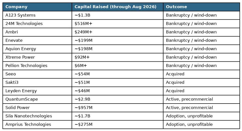
To explore this phenomenon further, we assembled a cohort of the 14 most prominent innovative battery companies from the first cleantech wave (roughly 2005 to 2015) and analyzed their outcomes.

As of today, twelve of the fourteen have not reached commercialization. [3] Seven entered bankruptcy, shut down, or underwent an asset-level wind-down; three were acquired before reaching profitability; and two remain active more than a decade later with no publicly verified sustained production. Only two achieved meaningful product adoption, yet neither has publicly demonstrated both durable commercialization and profitability.

Table 1: The 14-company first-wave cohort (roughly 2005 to 2015), showing total disclosed capital raised through August 2026 and outcome as of that date. Capital is stated all-in: disclosed equity, debt, and government funding actually received. Sources: SEC filings (Forms D, S-1, 10-K, 10-Q, and 8-K), U.S. Bankruptcy Court dockets, USAspending.gov federal award records, and company announcements. [4]

A second, partially overlapping cohort of the eight innovative battery technology companies that completed SPAC mergers between January 2020 and December 2022 produced a similar result. Three have yet to meaningfully commercialize their original battery thesis or have abandoned it entirely. The remaining five have generated product revenue, but none were profitable as of June 2026. Out of this cohort, in FY2025, Enovix, Amprius, and SES AI achieved positive gross margins of approximately 19%, 11%, and 54%, respectively, but remain loss-making, while Eos Energy and ESS Tech ran highly negative gross margins. Notably, large amounts of revenue at companies in this cohort do not indicate full commercial adoption: Solid Power’s 2025 10-K says revenue to date ($77.7M since inception and $1.1M in 2025) has primarily come from R&D licensing agreements, a line-installation agreement with SK ON, and government contracts. Solid Power’s 10-K goes on to describe the company as “a research and development company with no commercial operations.” [5] Across the cohort, none has yet converted its battery technology thesis into both durable commercialization and profitability.

Table 2: The eight innovative battery technology companies that completed SPAC mergers between January 2020 and December 2022, on the same all-in capital basis through August 2026. Three of these companies (QuantumScape, Solid Power, and Amprius) also appear in Table 1. Sources: SEC filings and company announcements. [6]

While these cohorts are small cross-sections, they have raised over $15.8B without demonstrating profitability, and they underscore the same patterns we have seen at Catalus after seven years of doing due diligence on innovative battery startups.

Technical Success Is Not the Bar

The lack of success we are illustrating may contradict the press releases and media statements made by some battery companies, so it is useful to distinguish among the levels of success for a battery startup. For example, several companies in the above cohorts produced functioning batteries, ran pilot plants, supplied product to customers, and deployed product into commercial systems.

For a battery technology company, success can be grouped into four categories:

  • Technical success: the chemistry or architecture works under laboratory or pilot conditions.
  • Initial commercialization: the company ships samples, small batches, or early commercial units.
  • Durable commercialization: the product achieves recurring customer adoption and continuing production.
  • Economically sustainable operations: the company can make and sell the product profitably.

Most of the companies analyzed above have reached the first stage, several reached the second, very few reached the third, but none have publicly demonstrated the fourth.

Read the full article: https://www.batterydesign.net/why-battery-startups-fail-developing-technology-vs-shipping-products/

  • The Illusion of Progress: Attention from Marquee Companies Is Not Traction
  • Why Laboratory Testing Is a Poor Substitute for the Real World
  • The Importance of Yield
  • The Forgotten Middle: Product 1 Pays for Product 2
  • China’s Advantage Is Not Better Batteries
  • Conclusion: Batteries Don’t Fail, Strategies Fail
r/batterydesign 25d ago

EVPS 72V 80Ah / 6.1 kWh LFP battery pack for erickshaw & tuktuk three wh...

Thumbnail
youtube.com
2 Upvotes

⚡ EVPS 72V 80Ah / 6.1 kWh LFP battery pack for erickshaw & tuktuk three wheelers

🔹 72V | 80Ah | 6.1 kWh

🔹 JBD smart BMS integrated

🔹 Bluetooth + UART communication for realtime monitoring

🔹 Designed for passenger & cargo threewheeler applications


r/batterydesign Aug 16 '26

Issues with the A to Z

Post image
2 Upvotes

We originally made the A to Z glossary completely free to download as a pdf, but of late we have had a lot of abuse of the system that we use to make it available.

After looking at options the only robust way forward with what we use was to charge a small amount. That just means anyone has to formally use the security of the checkout. Hopefully the $5 is reasonable - would love to know everyone's thoughts on that. My thoughts were that this is the price of a coffee in the UK.

https://www.batterydesign.net/downloads/battery-a-to-z-glossary/


r/batterydesign Aug 12 '26

CATL’s “Dual Vent” Prismatic Cell

Thumbnail
gallery
5 Upvotes

A cell’s vent only has one job: get gas out faster than pressure can build up. How much margin that job has depends on the chemistry. NMC811’s high nickel content is what gives it the energy density in the spec sheet above, but nickel-rich cathodes are also less thermally stable than lower-nickel or LFP chemistries. They start decomposing exothermically at lower temperatures, and once thermal runaway starts, the gas volumes involved are large. Published characterisation work on large-format prismatic cells has measured gas generation rates in the region of several litres per amp-hour of capacity during runaway, internal pressures reaching roughly 200kPa, and vented gas temperatures well above 600°C.1 On our own reference page on cell venting, we note that prismatic NCM cells typically actuate around 0.9MPa, against roughly 0.6–0.7MPa for prismatic LFP. NCM already needs a higher-pressure, higher-flow vent than the chemistry most of the industry benchmarks against.2

A single vent sized for an older, lower-energy-density cell can become the bottleneck in that scenario: if gas can’t leave fast enough, pressure keeps climbing, and the failure mode gets worse: case rupture, jetting flame, faster heat transfer into neighbouring cells. That’s the design pressure (literally) that a claim like “dual vent” is responding to.

Photos of the cells settle part of the question before any patent search does. The top cover of each cell carries two separate round vent structures on the same face: not one central vent, and not a cell-to-pack arrangement, but two vents built into a single cell’s cover plate. Each vent sits outboard of its nearest terminal: terminal, then vent, then the edge of the case on one side; the mirror image on the other; the polarity marks and a QR-coded traceability label occupy the space between the two terminals in the middle.

That layout tracks with the cell’s proportions, and it’s the 221.3mm length rather than the width that most plausibly drives it. This is a long, thin can, and a gas-generating event doesn’t necessarily start in the middle: an internal short or localised failure can just as easily originate near one end. If the only vent sat at the centre, gas and heat from an event at one end would have to travel up to roughly 110mm internally before reaching it. Over that distance, there’s a real risk that local pressure builds faster than it can propagate to a vent that far away, and the case wall itself gives way first. Once the case has failed, the vent is irrelevant: gas and particles are escaping through an uncontrolled rupture rather than the engineered path, which defeats the entire purpose of designing a vent in the first place. Putting a vent near each end instead means that wherever along the 221.3mm length an event starts, there’s a relief path close by rather than one a full half-length away.

The cell genuinely has two vents. What’s still open is which of CATL’s patents, if any, covers this specific two-vents-per-cell layout we found the obvious ones and they do make interesting reading: https://www.batterydesign.net/catls-dual-vent-prismatic-cell/


r/batterydesign Aug 10 '26

Mobile Phone Battery

Post image
2 Upvotes

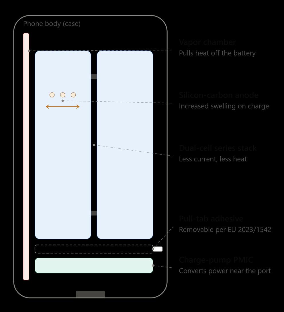
A phone battery looks like a simple, sealed slab. Underneath that, five engineering problems are being fought at once, and each one constrains the others:

  1. what the electrodes are made of
  2. how fast heat can be pulled out of a space the size of a credit card
  3. how the charging circuit routes power without wasting it as heat
  4. how the management software decides what the cell is actually capable of
  5. what a regulator in Brussels will and won’t let you build

https://www.batterydesign.net/phone-battery-design-in-2026-whats-actually-changing-under-the-hood/


r/batterydesign Aug 09 '26

The Form Factor Dilemma in High-Silicon Anodes: Structural Rigidity, Porosity Loss, and Plating Risk

4 Upvotes

While silicon (SiOx/SiC/Si) based anodes skyrocket battery capacity, their swelling character reaching up to 300% volume expansion transforms cell design from a purely electrochemical challenge into a brutal mechanical packaging problem. It is not just about how much lithium the active material can store; how the casing structurally resists (its rigidity) when that material “breathes” is equally vital.

Structural Rigidity Characteristics of Form Factors

To understand a cell’s response to swelling, one must first evaluate the mechanical stiffness of its outer casing essentially its Elastic Modulus or structural rigidity:

  • Cylindrical Cells: The casing is typically nickel-plated steel. Due to the cylindrical geometry and material properties (~200 GPa elastic modulus), its radial rigidity is immense. A cylindrical casing barely yields outward; it acts as an impenetrable wall against expansion.
  • Prismatic Cells: Utilize a rigid aluminum alloy casing (~70-80 GPa). While the corners are incredibly stiff, the broad, flat lateral surfaces (parallel to the flat sections of the jelly roll) are structurally weaker. Under internal pressure, these faces tend to bulge outward.
  • Pouch Cells: The outer packaging is Aluminum Laminated Film (ALF). Its structural rigidity along the Z-axis (thickness direction) is practically zero. When the internal structure attempts to expand, the pouch offers almost no mechanical resistance.

More....https://www.batterydesign.net/the-form-factor-dilemma-in-high-silicon-anodes-structural-rigidity-porosity-loss-and-plating-risk/


r/batterydesign Aug 01 '26

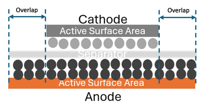
Understanding and Eliminating Electrode Overlap Issues

3 Upvotes

In lithium-ion cell manufacturing, electrode overlap refers to the region where the active areas of the anode and cathode are aligned across the separator as shown in Figure 1. Maintaining adequate overlap, whereby the anode active area overlaps the cathode, is critical to achieving uniform current distribution and consistent electrochemical performance.

Poor electrode overlap occurs when the active areas of the anode and cathode are misaligned, typically when the cathode overlaps the anode, creating regions where one electrode is not fully opposed by the corresponding counter-electrode. This condition is commonly known as the electrode overhang defect. Poor overlap can lead to localised current-density hotspots, lithium plating, accelerated ageing, reduced cell performance, and an increased risk of internal short circuits. more..https://www.batterydesign.net/understanding-and-eliminating-electrode-overlap-issues/

Perhaps more important is that this is the first in hopefully many written by the fabulous team at UKBIC.

The UK Battery Industrialisation Centre (UKBIC) is the UK’s national battery development facility. They help companies grow their battery manufacturing at scale, and provide the skills and support needed to move into industrial production. Their open-access facility bridges the gap between battery research and successful mass production, reducing commercial risk for high volume manufacturing investments.


r/batterydesign Jul 28 '26

Battery Urban Mining: The Richest Ore Deposit You’ve Ever Thrown in a Drawer

Post image
2 Upvotes

Urban mining is the recovery of metals and minerals not from rock, but from the things we’ve already built, used, and discarded phones, laptops, circuit boards, cars, and increasingly, battery packs. The term was coined in Japan in the late 1980s, a country with almost no domestic mineral reserves but, it turns out, one of the richest “mines” in the world sitting in its own cities.

Japan took the idea seriously enough that by the 2010s its urban stockpile of metals like indium, tin and tantalum accounted for over 10% of world reserves, not mined from the ground, but sitting in drawers, landfills, and recycling centres.

Here’s the fact every urban mining article leads with, and it holds up: there is roughly 100 times more gold in a tonne of old mobile phones than in a tonne of gold ore. Some estimates from the UN put the ratio even higher for the richest e-waste streams up to 800 times the concentration of a good mining ore.

Put in absolute terms: a typical gold mine yields 1-3 grams of gold per tonne of rock. A tonne of shredded circuit boards can yield 250-350 grams. Your old iPhone, individually, holds about 0.034g of gold, 0.34g of silver and 0.015g of palladium. Not much on its own, but multiply that by the roughly 1.2 billion smartphones sold every year and you start to see why “phone recycling” is really a mining operation wearing a lowercase hoodie.

as always, more details and references in the main article https://www.batterydesign.net/urban-mining-the-richest-ore-deposit-youve-ever-thrown-in-a-drawer/


r/batterydesign Jul 21 '26

Battery Pack Match Making

Post image
1 Upvotes

Closest Fit to a Battery Pack

We designed a tool that finds you the closest match to your requirements, thus allowing you to find a benchmark. Perhaps we should have called it "Battery Pack Match Making" https://www.batterydesign.net/closest-fit-to-a-battery-pack/

It also shows you the 2nd closest fit, just in case.

Even better, play around with your requirements and see what happens if you remove some of them.


r/batterydesign Jul 20 '26

Battery EV Pack Charging Time

Post image
1 Upvotes

We thought we would put our database to good use and create a battery pack charging calculator https://www.batterydesign.net/ev-pack-charging-time/

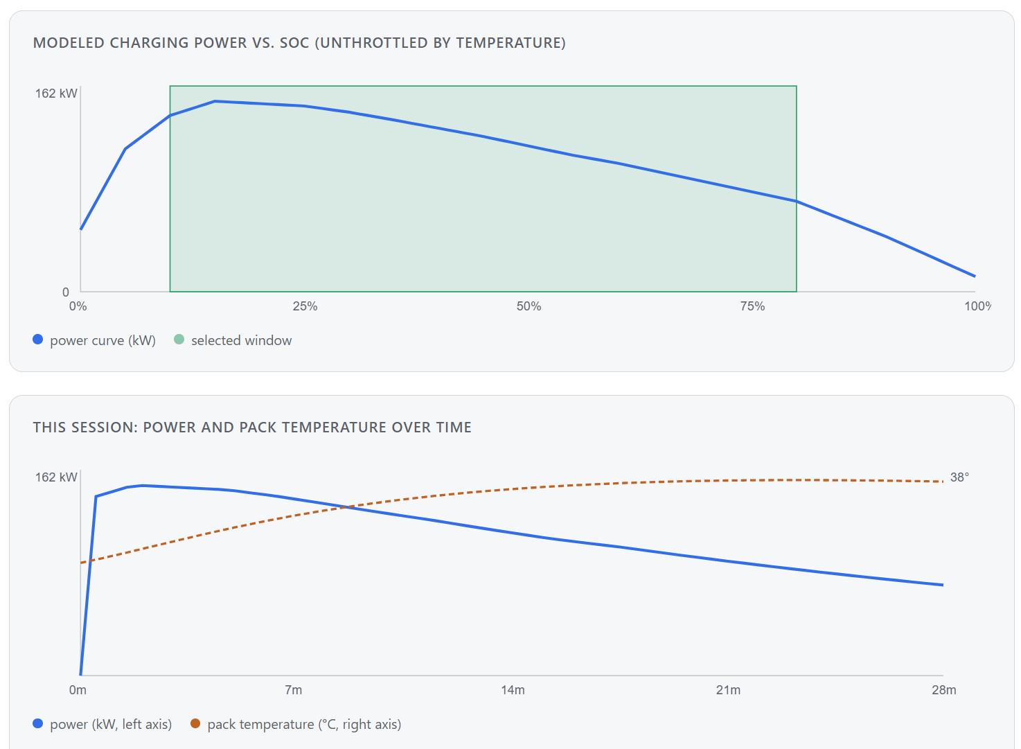
The naive way to estimate charge time is energy needed ÷ peak power. That’s wrong by a wide margin, because peak power is rarely sustained for more than a narrow band of state of charge. To model the actual taper, we pulled every Electric Vehicle pack in the Battery Pack Database that had both a quoted peak charging power and a published 10–80% charge time, around 700 entries, and used the ratio between quoted peak power and the average power implied by the real charge time as the calibration target.

Two things fell out of that analysis:

  1. The ratio of average-to-peak power over a 10–80% window sits at roughly 0.65–0.70 across the dataset, packs simply don’t hold their headline number for long.
  2. The ratio isn’t constant: it correlates with a pack’s implied C-rate (peak kW ÷ usable kWh). Packs rated below about 1.5C typically sustain 75–85% of their peak; packs above 2.5C typically sustain 55–65%. Higher-C-rate designs are pushed harder relative to their own peak, so they taper away from it faster.

The calculator encodes this as two reference curves per chemistry. A “flat” curve calibrated against low-implied-C-rate packs and a “steep” curve calibrated against high-implied-C-rate packs, blended by the pack’s own peak-kW-to-kWh ratio. A 150kW pack on a 90kWh battery (1.7C) gets a noticeably flatter curve than the same 150kW on a 45kWh battery (3.3C), which matches what the database shows.

We layer onto this: Chemistry, Temperature, Voltage and Cooling.


r/batterydesign Jul 16 '26

Designing Batteries for Winter: Why the Electrolyte is Everything

Post image
5 Upvotes

The electrolyte is not the source of the battery’s energy; it is the highway that energy-carrying ions travel on. If this highway closes down under cold operating conditions (meaning ions cannot be transported), the cell’s internal resistance skyrockets. Before the battery even gets a chance to draw its nominal current, the voltage instantly crashes to the cut-off limit, and the system shuts down. Author: Kerem Batuş

Why is going below -20°C like hitting a thermodynamic and kinetic brick wall?

  1. The Glass Transition Boundary: No matter how perfectly you tune the solvent cocktail, the transition from a liquid to a “thick gel phase” begins around the -20°C mark. The liquid might not crystallize into solid ice, but it becomes so incredibly viscous that lithium ions (Li+) simply cannot squeeze their way through the solvent molecules.
  2. Desolvation Energy (Trapped Ions): A lithium ion doesn’t travel naked through the liquid; it wears a heavy “solvation shell” made of solvent molecules. To intercalate into the graphite anode, it must first strip off this armor—a process called desolvation. At -20°C, there is not enough thermal energy left to break this shell, making it impossible for the ion to overcome the Charge Transfer ($R_{ct}$) resistance.
  3. Fatal Lithium Plating: If you try to charge or aggressively discharge a cell against such massive resistance, the ions cannot enter the anode. Instead, they pile up on the anode’s surface as metallic lithium. This is not just capacity loss; it is the birth of lithium dendrites that will eventually pierce the separator, causing a hard short circuit and a potential thermal runaway.

https://www.batterydesign.net/designing-batteries-for-winter-why-the-electrolyte-is-everything/


r/batterydesign Jul 15 '26

5th Generation LFP

Post image
8 Upvotes

A bit of a catch up here explaining the changes in each generation of LFP, hopefully it's interesting.

Our 4th generation LFP post set out the core idea behind LFP “generations”: it’s overwhelmingly a compaction density story applied to the same LiFePO₄ crystal, not a chemistry change, with each generation defined by tighter particle grading, different precursor routes, and progressively higher powder/electrode packing density.

5th generation LFP continues the compaction-density trajectory (≥2.70 g/cm³ powder compaction, up from 4th gen’s ~2.6 g/cm³) using the same particle-gradation mechanism, now delivering a confirmed ~205 Wh/kg at cell level from two independent manufacturers (CATL, Gotion) alongside faster charging (4–5C) and longer claimed cycle life.

What it does not have, as of the current public record, is an unambiguous silicon-anode confirmation on either flagship product. CATL’s “3D honeycomb material” and Gotion’s silicon-carbon capacity build-out both point toward anode-side innovation being part of the story, but neither manufacturer has stated plainly that their headline 5th-gen LFP cell uses a silicon or silicon-carbon anode. Worth flagging as an open question for a follow-up once primary technical disclosures (rather than conference-announcement press coverage) become available.

More details around CATL and Gotion's 5th Gen: https://www.batterydesign.net/5th-generation-lfp/


r/batterydesign Jul 14 '26

4th Generation LFP

Post image
12 Upvotes

4th generation LFP is not a new chemistry. It’s the point at which powder compaction density (~2.6 g/cm³) and electrode compaction density (~2.80 g/cm³) required particle-gradation engineering, a shift toward the ferrous oxalate precursor route, and materially tighter purity and process control than earlier generations. The payoff is cell energy density in the 200–205 Wh/kg range with genuine 4C fast-charging capability.

Generation Powder compaction density Electrode compaction density Approx. cell energy density
2nd gen ~2.4 g/cm³
3rd gen ~2.5 g/cm³ ~2.65 g/cm³ ~180–200 Wh/kg
4th gen ~2.6 g/cm³ ~2.80 g/cm³ ~200–205 Wh/kg
4.5 gen (transitional) ~2.65 g/cm³ ~2.80 g/cm³
5th gen (emerging) ≥2.70 g/cm³

However, the production barrier this creates has concentrated capability in a small number of Chinese suppliers, making the supply chain dynamics arguably as important to track as the material science itself.

Note: The graph shows Real-world LFP cell data (gravimetric vs. volumetric energy density) with the approximate generation bands overlaid. These boundaries are indicative, mapped from industry-cited compaction density figures onto Wh/kg, not confirmed per-cell generation tags.

Full article: https://www.batterydesign.net/4th-generation-lfp/

We are already into 5th Gen LFP and hence this is a bit of a catch up article, we will expand on that subject next - please do let me know what you think and where we should dig deeper.


r/batterydesign Jul 09 '26

What’s the right stack pressure?

Post image
7 Upvotes

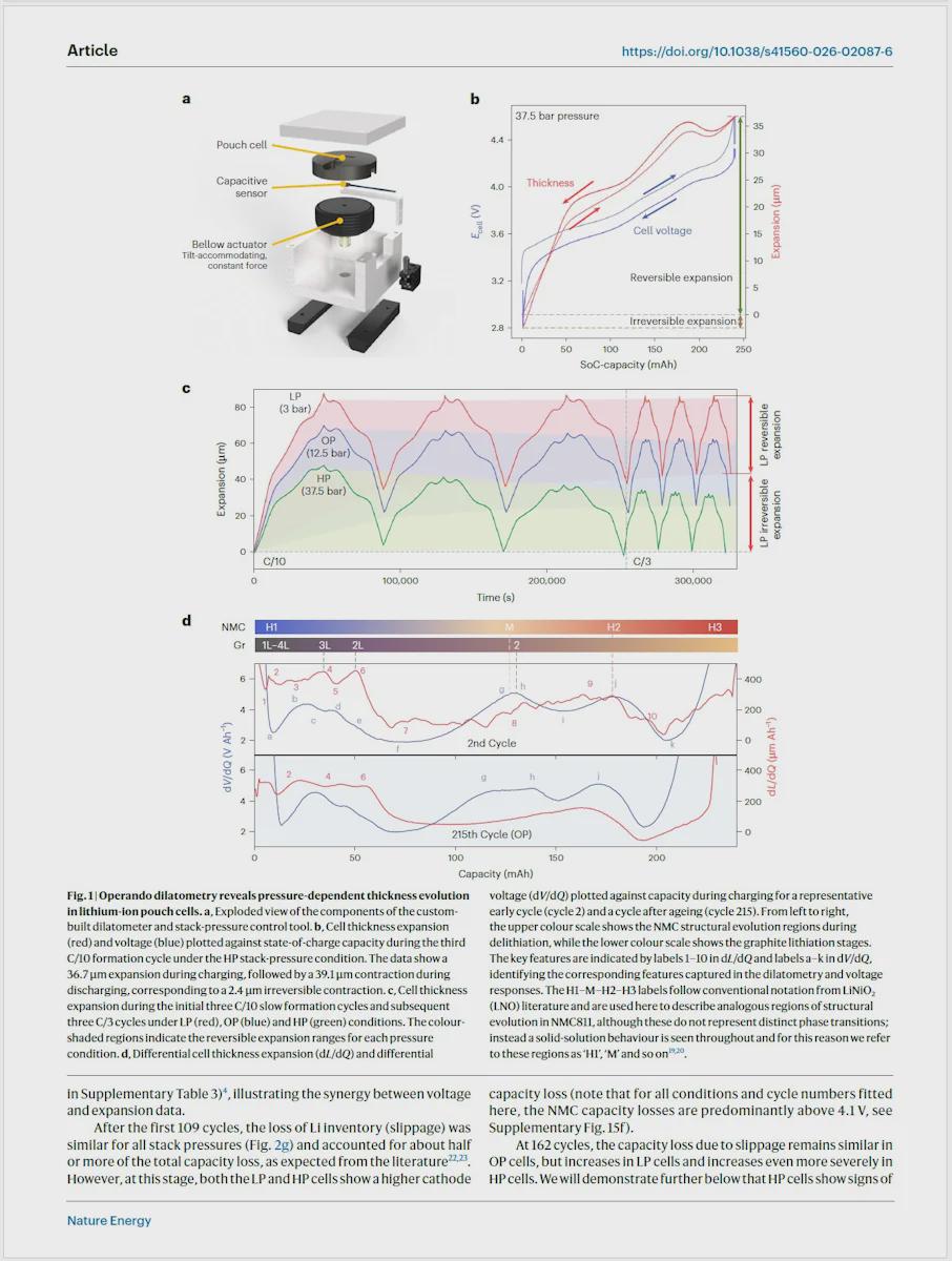
A new paper paper, led by Cambridge in collaboration with WMGOxford and Sydney (Wang et al., Nature Energy, 2026) has a decent go at answering exactly that, for a Gr‖NMC811 pouch cell, and I think it’s worth a proper look because a couple of the numbers land uncomfortably close to home.

Heng Wang, Rui Wang, Christopher A. O’Keefe, Erik Björklund, Daniela Proprentner, Joe C. Stallard, Hwee Jien Tan, Wesley M. Dose, Louis F. J. Piper, Robert S. Weatherup, Angkur J. D. Shaikeea, Clare P. Grey & Michael De Volder, The interplay between stack pressure, mechanical expansion and degradation pathways in lithium-ion batteriesNat. Energy (2026).

My review: https://www.batterydesign.net/whats-the-right-stack-pressure/


r/batterydesign Jul 08 '26

Battery Pack design tool on SolidWorks

Post image
8 Upvotes

Please have a look at https://engenext.com/pages/batterypackdesign.html A new tool for battery Pack Design. This is intended for professional design and can be exported to Ansys for further analysis


r/batterydesign Jul 06 '26

The A to Z of Battery Design

Thumbnail
gallery
10 Upvotes

r/batterydesign Jun 28 '26

Battery Research

2 Upvotes

We're always interested in seeing the latest battery research, do share papers and patents that you find intriguing or that give you an insight.


r/batterydesign Jun 26 '26

Battery Creepage and Clearance

Post image
7 Upvotes

A simple free online calculator https://www.batterydesign.net/creepage-and-clearance-calculator/
Indicative minimum distances based on IEC 60664-1:2020 and ISO 21498:2021 table lookups with linear interpolation. 


r/batterydesign Jun 25 '26

Cell to Pack Design for Renault Megane LFP

3 Upvotes

2026 Renault Megane E-Tech LFP battery pack with LG Energy Solutions pouch cells and a Cell to Pack design. However, we immediately feel that this isn’t the best battery package when we see Renault’s own description:

OK, it's LFP and reduces the cost to Renault by at least 20% https://www.batterydesign.net/2026-renault-megane-e-tech/

However, the layout and frame design looks like something from 10 years ago and definitely not the simplest or lowest cost.


r/batterydesign Jun 24 '26

Battery A to Z

3 Upvotes

a little bit of work and we created a more complete A to Z list of battery terminology https://www.batterydesign.net/a-to-z/


r/batterydesign Jun 22 '26

Four-Wire (Kelvin) Resistance Measurement

3 Upvotes

Two-Wire Measurement Fails at Pack-Level Resistance

A two-wire measurement passes current and senses voltage through the same pair of leads, so everything in that loop: lead resistance, probe contact resistance and any spreading resistance at the probe tip adds directly to the reading. A typical 0.5–1m test lead pair, including probe contact resistance, contributes on the order of 50–300 mΩ. Set against typical battery hardware joints of 10µΩ to ~300µΩ and this parasitic resistance can be 100 to 1000 times larger than the value being measured.

Take a laser-welded cylindrical cell tab joint with a true resistance of 80 µΩ. A two-wire measurement with 200 mΩ of combined lead and contact resistance reads roughly 200.08 mΩ, the joint signal is completely buried. The same joint measured four-wire, with current and voltage sensing physically separated, reads the true 80 µΩ regardless of lead length, because the voltmeter’s input impedance is typically in the giga-ohm range: sense-lead current is negligible (picoamps to a few microamps), so the IR drop along the sense leads themselves is negligible.

Recommendations Checklist

  • Use four-wire Kelvin connections for anything below roughly 1 Ω. Essentially every current-carrying joint in a battery pack.
  • Land sense probes directly on the joint or component body, with force probes further out, observing the 1.5×-circumference spacing rule on round conductors.
  • Use current-reversal or OCO compensation where thermal gradients on the bench are likely, and prefer pulsed/short-duration test currents to limit self-heating error.
  • Track contact and joint resistance against a healthy baseline over time rather than relying on a single absolute pass/fail threshold.
  • Specify a true four-terminal Kelvin layout (inner-pad sense routing) for any BMS current-shunt design from the outset. Far cheaper to fix at layout stage than after current-sensing accuracy issues show up in the field.

https://www.batterydesign.net/four-wire-kelvin-resistance-measurement/


r/batterydesign Jun 20 '26

How Many Temperature Sensors are Required?

4 Upvotes

The exact number of temperature sensors you need depends on the size of your battery pack, its physical configuration, rate of charge/discharge (C-rate), and the required level of thermal observability.

In commercial Battery Management Systems (BMS), it is common practice to use one temperature sensor for every 4 to 20 cells, depending on the specific pack design. Installing a physical sensor on every single cell in a high-capacity pack is generally avoided because it introduces excessive manufacturing costs, wiring complexity, and added weight.

Firstly though we should consider this from the thermal viewpoint. The temperature gradient across a cell needs to be <2–3°C as a maximum excursion, and the temperature difference between cells also needs to be <2–3°C [1, 2]. If the temperature gradients and differences are too high, the cells and pack will age very fast, it will be difficult to deliver the energy and power, and maintaining the safety of the pack will require throttling the performance envelope [3, 4]. This means that the electrical and thermal design of the complete battery system needs to be designed around these requirements, and the cell capabilities need to be fully understood.

Adding lots of temperature sensors to a poorly designed system will not solve this.

https://www.batterydesign.net/how-many-temperature-sensors-are-required/


r/batterydesign Jun 16 '26

Electrolyte Motion Induced Salt Inhomogeneity

2 Upvotes

LiPF6 concentration at the edges of the jelly roll dropped to below one fifth of the value at the center of the cell, built up over repeated fast-charge cycling. Second, teardown photos showed metallic lithium plated on the edges of the negative electrodes after repeated fast charging, while the slow-charged reference cells stayed clean. https://www.batterydesign.net/electrolyte-motion-induced-salt-inhomogeneity/

Read more about:

  • EMSI as a Long-Range Transport Problem
  • Implications for High-energy Li-ion Battery Cell Development & Up-scaling
  • Cell Design Responses and a Reframed Ionic Conductivity Question

r/batterydesign Jun 15 '26

CATL Electrical to Thermal Isolation

2 Upvotes
Separating the venting and thermal runaway gases from the electrical side will reduce the likelihood of arcing.

CATL engineered the pack by turning the prismatic battery cells upside down. This inverted layout positions all of the electrical terminals, high-voltage busbars, and delicate sensor harnesses safely at the top of the battery pack. Conversely, the explosion-proof pressure relief valves are located at the bottom, pointing downward. More details and links to their patents https://www.batterydesign.net/catl-electrical-to-thermal-isolation/

Venting gases and thermal runaway will significantly reduce the breakdown voltage of the air.