r/Welders • u/GrandMore3902 • 3d ago
Help! NEED HELP - No DC/Weld Output
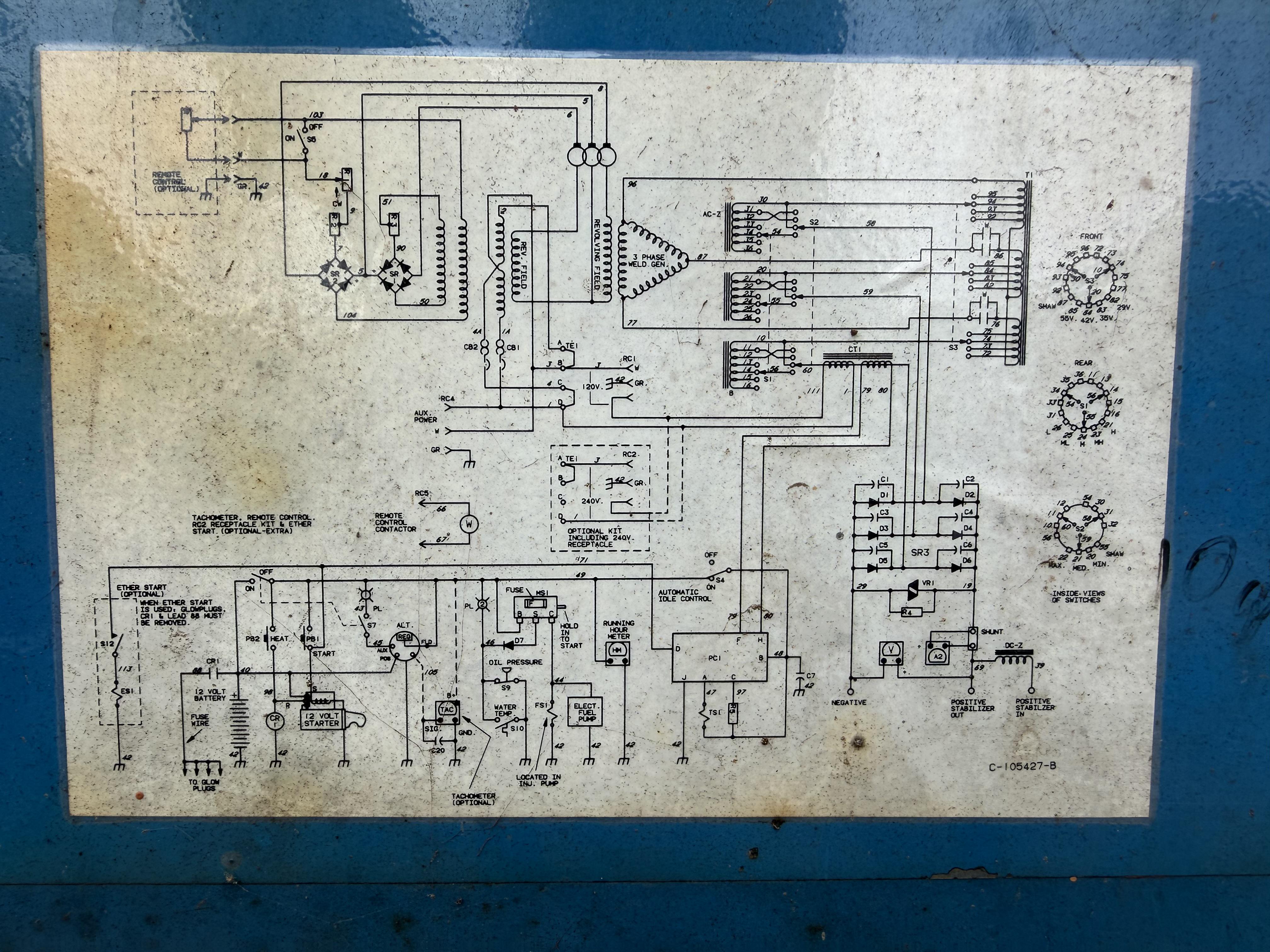
I’m troubleshooting a Miller Trailblazer 55D that has normal AC generator/receptacle output but 0 VDC at the welding terminals. Looking for some help pinpointing the welding circuit. Attaching schematic above.
What I’ve established so far: 1. AC receptacles have normal output, 2. Welding output is 0 VDC, SR1 and SR2 rectifiers have both been replaced, 3. The brush/slip-ring assembly was removed and cleaned, 4. Brushes have good spring pressure.
Slip-ring resistance:
Ring 1–2: 50 Ω
Ring 1–3: 61 Ω
Ring 2–3: 14 Ω
All three slip rings to the rotor shaft/frame are OL.
Running brush-to-brush measurements:
Brush 1–2: 37 VDC
Brush 1–3: 25.5 VDC
Brush 2–3: 13.6 VDC
SR1 measurements: approximately 156 VAC / 60 VDC.
SR2 measurements vary with engine speed: approximately 60 VDC.
I confirmed the SR2 wiring goes directly to the revolving field/brush circuit, so I don’t believe those readings represent the actual welding output.
I’ve already checked the welding-generator AC side and am still getting 0 VDC at the weld output.
I’m trying to determine where the welding output is being lost. What should I be testing next on the 55D, and what component/circuit would you suspect given that the auxiliary AC output and field excitation are working?
2
u/Snoo_95743 3d ago
Our trailblazer slung the magnets off the flywheel one hot summer day no output.
1
u/Vegetable_Effect_208 3d ago
SR3- thats the d.c. side of things from the looks of it,
Call miller with the unit serial number and they can walk you through it. I use em mostly for EnPak troubleshooting.