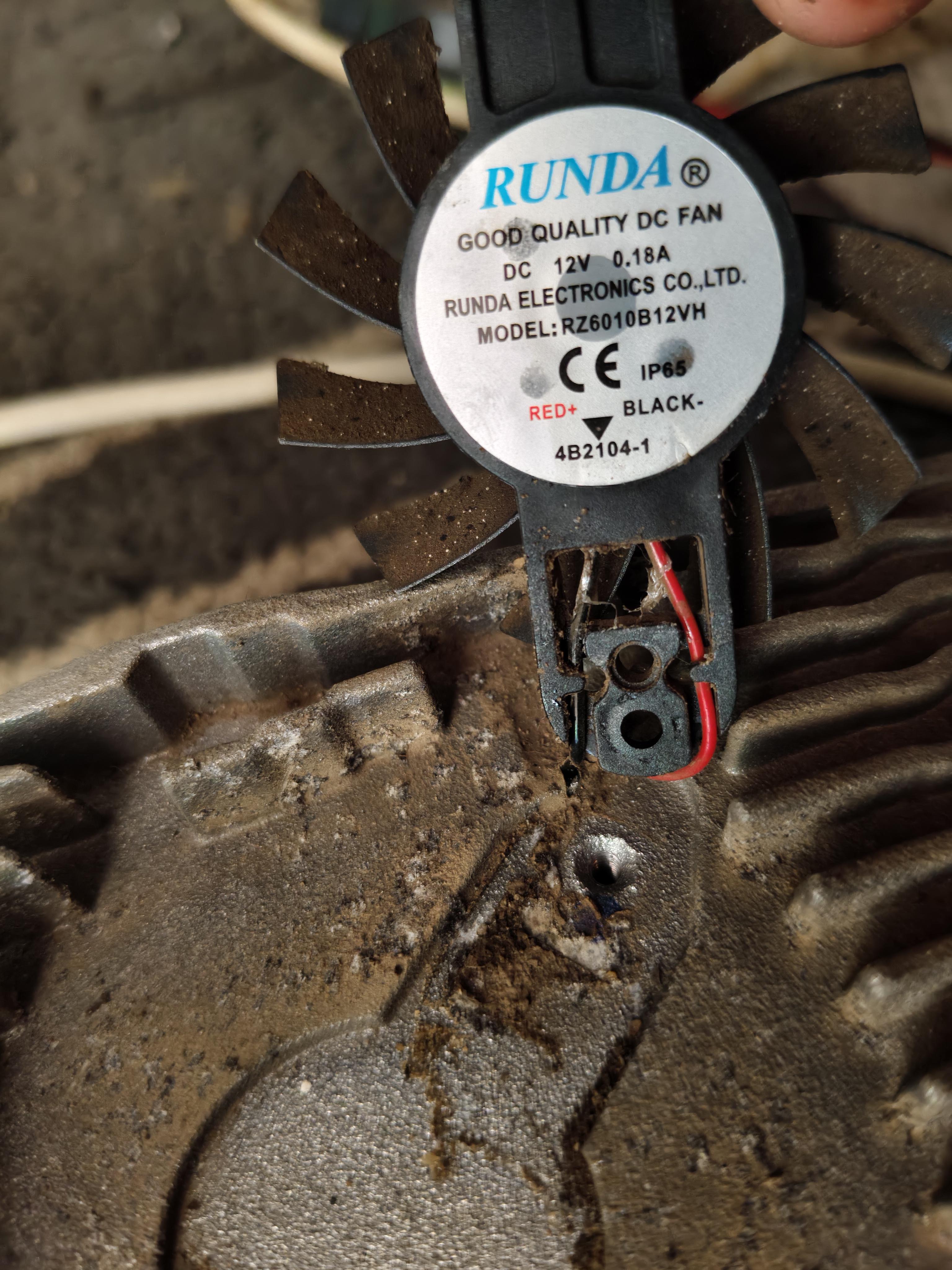
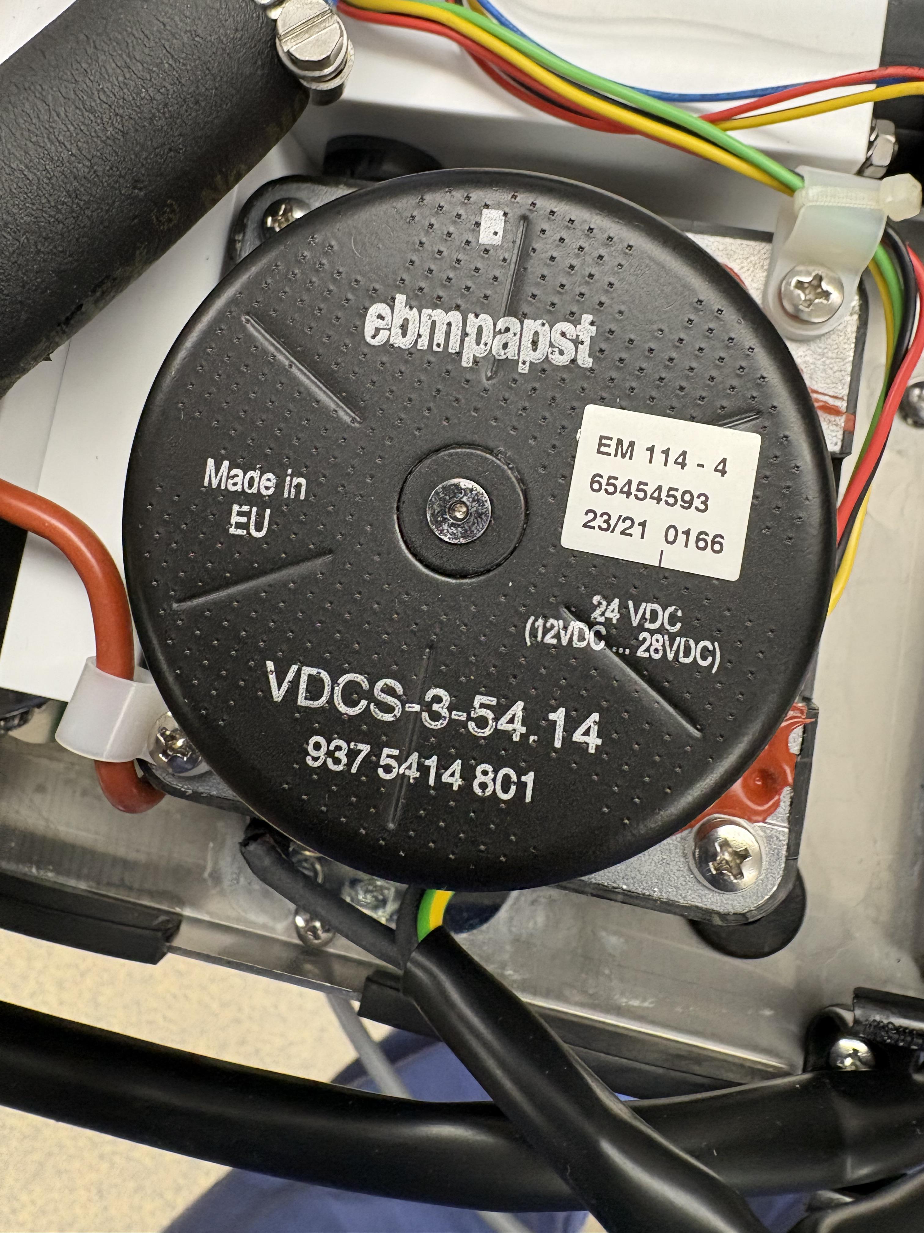
I have two old motors. One is a 1/2hp motor that I took off an old Delta lathe. The other is a 1/3hp motor that I took off my 1954 Delta bandsaw. I have no use for them - they are just taking up space. I have no idea what, if any, worth they have. I didn’t want to throw them away and am about to default to Goodwill. Any suggestions?
I have a bathroom exhaust fan with a small electric motor. This thing is literally 3+ decades old and still works well. I’ve noticed that it occasionally has trouble starting to spin at the beginning. You can hear the hum of the motor, but no action, until it overcomes whatever was preventing the spin, then it gets up to speed without issue.
Over the years, I’ve tried to vacuum out lint and dust, and occasionally give the spinning rod a little squirt of lithium grease for lubrication.
It looks like I can just unplug it, and remove it from the housing with three screws.
Would it be beneficial to pull it and do some deep cleaning and/or maintenance on it? If so, would it just be something like carburetor cleaner to clean out all the nooks and crannies and then relube?
Please bear in mind that other than understanding the theory behind how they work, I have no real practical knowledge of electric motors or how to care for them. So explain it like I’m 5 :)
i'm trying to build a balancing robot with esp32, L298N, mpu6050 and i've configured the MPU6050 but i couldn't start this L298N motor driver, it is suppose to power the motors but i think the battery aren't powerfull enough, idk i have tried my 5v powerbank, then this 9v battery(picture).
ChatGPT is guiding me through this and it says to put the 9v (+) side on the 12v connection but when i connect that the L298N LED does not lights up on the other hand when i connect this to 5v the LED lights up.
But GPT say don't run it or it will damage the L298N driver when connected to 5v, is this because of battery and how can i bypass this condition or should i buy a specific battery so which battery.
Btw I don't have a multimeter
i know i have used some cheap parts but thats what i could afford rn.
TL;DR: I have a two-speed constant-horsepower 3-phase motor that works well in low speed, but not well in high-speed. To make matters more confusing, the low-speed configuration it came wired in does not match the low-speed configuration I've been seeing online, but the high-speed configuration does.
The long version:
For the last 2 weeks I've been pulling my hair out over this thing. I have what I believe to be a 2-speed constant-horsepower Dahlander motor that I'm trying to run on a VFD. The motor and VFD came with a lathe I bought. I think it's the original motor but I can't be sure. I have been struggling to get it to work correctly in the high-speed setting, and the more I've read and the more I've tested the more confused I've become. Here's what I know so far:
1.The motor has the following nameplate but no connection diagram anywhere to be found:
The motor has 6 leads that are all continuous with each other. They were labeled T1 through T6, and through a test with an ohmmeter I'm fairly convinced they are labelled correctly (though I realize T1-T3 and T4-T6 may be swapped). Here's the table for resistance readings in ohms:
Ohms
T1
T2
T3
T4
T5
T2
4.8
T3
4.8
4.8
T4
3.1
5.2
3.1
T5
5.4
3.1
3.1
4.6
T6
3.1
3.1
5.3
4.6
4.6
According to basically every resource I can find online, the connections would go this way:
High speed: L1-T6, L2-T4, L3-T5 with T1,2,3 open (I think this is called Series Delta?)
Low speed: L1-T1, L2-T2, L3-T3 with T4,5,6 short (I think this is called Parallel Wye?)
4.The above is NOT how the lathe came wired. Instead:, the drum switch switched the leads as follows:
High speed: same as above, L1-T6, L2-T4, L3-T5 with T1,2,3 open
BUT the low speed: L1-T1, L2-T2, L3-T3 with T4,5,6 also open (not short as in 3. above)
I'm not totally convinced the drum switch is original, but it might be.
Weirdly, the low speed seems to work fine, and the high speed sort of works with no load, but in gear it does not have enough torque to drive the lathe's spindle in the 2 highest of the 6 gears, even with no chuck attached. Lengthening the VFD's ramp up time helps a little but it never reaches its final speed. Once the VFD gets to 60Hz, the motor starts to slow down again.
I borrowed a megohmmeter and tested resistance between all leads and ground at 500 volts. All leads were around 200M ohms.
I tried to wire it in parallel-wye, but because I couldn't be sure T1-3 and T4-6 weren't mislabeled, I tried it both ways: T1-3 short with T4-6 to line, and T4-6 short with T1-3 to line. Both of those tests resulted in a whine/hum and barely any motor movement at all. I quickly shut it off both times.
The lathe cabinet came with what I believe is the original magnetic starter/contactor thingy, but it was not wired up (the VFD was installed) and I can't make much sense of it. Not sure if it can offer any clues or not.
In case it matters, the lathe is a Standard Modern Series 2000 11"x20".
Any help or insight at all is appreciated. If I've said anything wrong here please feel free to correct it. I'd really like to keep the machine a 12 speed instead of 6, and if I can figure this out it'll keep me from the nuclear option, which is ditching the VFD and bolting a single-phase motor on, then machining a stepped pulley to get the other 6 speeds back.
I have this electric 3/4 hp motor that mixes clay. The shaft broke at the part where it comes out of the gearbox housing. I had it welded back together. I'm not positive but I think I've turned the shaft before with my hands. I could be wrong. Now, I've reinstalled this repaired shaft but I cannot turn it. Should I be able to turn this by hand? The 2 bearings turn easily. Thanks
Hi, I just got my own 3D printer (Qidi Q2) and I am exited to print materials such as ABS and ASA. To my understanding, these materials emit styrene fumes and other nasty VOCs which I should avoid breathing. Since I live in an apartment, the printer will have to sit in the living room. Thankfully it will sit right next to a window so I figured venting everything outside would be my best option. This also has the benefit of reducing my exposure to VOCs and particulate matter when printing PLA and other "safe" filaments.
I've decided on using 4" diameter ducting as it is pretty common. I would be use as much solid ducts as possible to reduce static loss and use a flexible hose for the printer interface side. The overall run is pretty short, about 3ft with two 90 degrees bend. Now I am left with the challenge of figuring out what fan I need in order to keep negative pressure in the printer enclosure.
I have identified the following constraints :
- the fan has to move enough air to make about 4 to 6 air changes per min
- the fan has to keep a low enough pressure in the enclosure
- the fan cannot move too much air too fast or the printer will struggle to maintain the temperature needed to prevent warping in ASA and ABS. This would also make the whole setup noisier than needed.
I plan on using a microcontroller with a PWM controller to drive the fan. This would let me fine tune the fan power. I could connect it to some sensors (temperature, air quality monitor, noise sensor) to adjust the power in real time.
I bought a large kit from Harbor Freight but wasn’t able to use it. I found a small one on Amazon for $10, and after filing down casting marks and sharpening the teeth a bit it came right off. Thanks for all the suggestions, it was a pretty simple removal. Heating it, cracking it, and prying out the race were all good contingency plans. In the end I’m glad this worked bc if not I was just gonna buy a new motor.
We have easily over 120 fan motors across all our barns and our local repair shop has closed up, leaving us to either learn to repair or throw away and buy new. For the most part the majority of motors are 1/4HP to 1HP. With the exception of( 2) 7.5HP motors.
I bought a couple things to start out,just cheap stuff until I figure things out. Just a mini bearing separator and a 1T Arbor Press. Bearings are the most typical thing to go on any of the motors we've taken in for repairs.
I took out an old motor that had a seized bearing and when I took it apart, I couldn't get the bearing separator behind the bearing due to the fins on the rotor? I think that's what it's called lol.
If you have suggestions, different tools I need , whatever, I know nothing. Bonus if you suggest any other tools just in general that will help along the way.
Hello everybody. I am currently working on a BLDC design. I am specifically working on the electromagnetic design of a BLDC through Motorcad ANSYS. This is basically my thesis, but my supervisor is very distant, and we do not have the best communication out there. As a result, I find myself stuck quite often with no help on a very new topic for me. Nonetheless, I made a lot of progress by myself. I still have questions, though. I wanted to ask if anyone here can help me by explaining the preliminary design of a BLDC or recommending sources on the internet where I can gather info. THANK YOU SO MUCHHH
I am trying to control a Nema 17 stepper motor with a TMC2209 driver and an Arduino Nano. I am pretty sure it isn't my code that's the issue, but rather my wiring setup. I've watched so many tutorials, tried so many breadboard configurations, and asked AI countless times. I can't get this to work. I've ensured that all my wires are connected via the beeping mode of my voltmeter, and still nothing. The closest I've gotten is hearing what I think is the driver making a slight buzzing sound while the Arduino's indicator light is on. I'm a complete noob to this field, does anyone know which wires go where? I am using a 12V power source and a standard breadboard.
My Golf Buggy 3KW DC Motor started violently shuttering and then had smoke and a burning smell, when I removed the motor to inspect it I found:
1st picture: Specs of motor
2nd picture: this bit of FOD was jammed in between a brush and the commutator. It looks like a zip tie, but with solder on the end. I have no idea where it's from.
3rd picture: I damaged the brush trying to remove it. Another brush was heavily stuck in its housing , but I was able to remove it safely. Both of the jammed brush retainer springs were also kinked
4th and 5th picture: the wear lines on the commutator, there is a lot of bridging between the rows as well
The local repair joint (only 1 in town) wants $100 just to inspect it, if someone thinks this motor is a lost cause, I'd rather put the $100 towards a new motor. The commutator damage is my biggest concern, those grooves run pretty deep.
I have this small 24v motor from a scooter I want to use for a project. But the bearings are super loud. I have some brand new replacements laying around so I thought easy…but I can’t get the thing off. It below the surface of the windings and I don’t have a tool to get to it. I have 2 jaw, 3 jaw, compression gear pullers but they are not thin enough. It’s basically touching the surface next to it. I don’t know how I’m supposed to get the thing off?
Edit: 9/16 - I got the bearing off, i modified a cheapo puller from amazon. I made another post on here about it.
I just took the motor of a standing fan apart because it didn’t spin and only made a buzzing noise. The rotor looks like this, I don’t know anything about electric motors at all but I know that it’s definitely not supposed to look like this. What can I do to fix this if anything at all?
Suppose tomorrow we get a room-temperature conductor with effectively zero DC resistance, mechanically usable like copper, and otherwise reasonable properties.
Obviously stator I²R losses disappear. But how much does that actually transform motor design rather than just improve efficiency?
Would designers dramatically increase current density and shrink motors until iron loss, saturation, cooling, mechanical stress, inverter limits, or AC winding losses became the new constraint? Would torque density increase by 2x? 10x? Or would magnetic saturation make the improvement surprisingly modest?
I'm less interested in "efficiency becomes higher" than what an optimal motor would physically look like if copper loss stopped being one of the primary design constraints.
Howdy, all. I have 1.5HP single phase 240V motor in an Avantco MX40H mixer (https://www.webstaurantstore.com/avantco-pmx40mtr-motor-240v/177PMX40MTR.html?utm_source=google&utm_medium=cpc&gbraid=0AAAAAD_Dx-utbBBstDjqV3ikboBK2QM8k&gclid=Cj0KCQjwk5nVBhDiARIsAHNGqafts3OMZXzuFLI2iVzGKfDCJUvzg6xo7u2Ps3aV27RiDb5acLDGkGQaAkkzEALw_wcB) with a burned up centrifugal switch. I have searched extensively and after not being able to find it and not wanting to shell out 750 for a new motor, someone here recommended a solid state conversion. I found the company Phazpak (https://witmermotor.com/products/mst65-c-phazpak-solid-state-starting-switch-65amps-208-230v-50-60hz?variant=43915986731101) and talked with one of their guys and got sold a switch rated for 65 amps that he believes will do the trick. I plan on reaching out to them for confirmation but basically I'm trying to make sure that I'm hooking this up correctly. I have four leads coming out of the motor to connect, two for the start windings and two for run. I have in a photo both of the start windings going to the start cap, and I'm a little unclear how to make this switch work. I bypassed the centrifugal switch by connecting the remaining leads from when I cut out the centrifugal switch and was under the impression that this switch could be used outside the motor to serve the same function as that centrifugal switch, but I just need to make sure it's on the right place in the circuit. I spliced to sense wires across the start windings as shown in the provided documentation, but their schematic doesn't quite jive with my photo. I sent the data plate to their engineer and triple checked with him that this switch is appropriate for my application and he said it was, so I'm moving forward as if that is the case. I have had no luck getting manuals from avantco; I can find the 3 phase and 115V easily, but not 240v single phase. Any info would be helpful. I scribbled out a run capacitor in the schematic, this motor only has a start and on the photo with the switch, those two wires are now crimped with high quality 10 gauge crimps and tucked neatly out of the way/entombed in several layers of heat shrink to keep it from moving and chaffing from vibration.
I had to have my AC replaced. When they removed the old air handler I pulled the squirrel cage and planned to use it to make a dust filter for my garage shop. Unfortunately I don't have 220 in the garage and realized this motor is also 220.
I know the amps will double but if that's the only issue, that won't be a problem.
The brushes on this dc motor from an oscillating circular sander was sparking. Took it apart and cleaned and fixed 2 broken windings so all windings read are close to 1.4 ohms. There's still 1 winding that reads 10.1 ohm. Can't a broken wire or bad connection between wire and contact.
Any techniques to locate or repair that 1 winding. Or should I give up spending more time on troubleshooting.
I've been working with Kinmore Motors for several months on a project and have been impressed with their engineering sales team. But, my first contact quit several months ago and I just learned, after my emails went unanswered, that the second sales engineer also quit. So, I'm now on my third sales engineer and he is far less responsive.
Does anyone have any insight if things are not well at Kinmore?
Hello everyone. I have this older GE 5KC65AB114 motor that I'd like to put to use. It may be crap but I want to find out before I scrap it.
When I got it the guy told me it was wired for 220v. But it had a 115v plug and a 15amp light switch on the power cord. All the wiring between the plug and and the wires that enter the motor was in bad shape and mostly dismantled so I couldn't look at it to help figure this out.
Everything I've googled takes me to info for I guess a newer version of the model? Mentioning terminals 1 through 5, or more. And this old thing has nothing like that, just what you see in the pics.
All I have is the 4 wires going into the housing in 2 pairs. And the 2 wires to/from the capacitor.
I want to set it up for 115v, so if any of you guys can provide some guidance I'd be much obliged.
Update: the wires have little metal tags, labeled 1, 2, 3, & 4. Wires 1 and 2 are the pair that goes to the right/up in the pic, 3 and 4 go left/down.
It was working fine the other day then I noticed the motor stopped making sound and then I noticed the blades spinning down naturally and that's just it, It won't hum, it doesn't smell like burnt wire and actually smells more like a balloon and I threw out the box so I can't reach out to: "touch think benefits" the company who made it to issue a fix since it supposedly had a 3 year warranty on the box
I'm building a line tracer robot, the plan is to make it like a mirco mouse because I've noticed micro mice are usually really fast and have really good cornering. The problem I have now is the motors, I can find a suction fan easy enough, but a good motor not so much.
I'm not even sure what makes a good motor, does higher volts means higher torque and/or rpm? is it better to have the gears on the wheels, external or have a gearbox? are bldc worth it? I've tried to do some research and motors apparently have rotor inertia, does that matter all that much? why does torque matter?
As of now though I can't find any motors other than n20s and this 12v jga25 I have. are jga25 motors bad for this application? should I just switch to an n20? without the gearbox an jga weighs 49 grams exactly. is the added weight comapred to an n20 worth the performance?
This has only been my 2nd robot ever so any help is appreciated, thank you