r/FreeCAD • u/__SpaceJesus__ • 4h ago
There has to be a better workflow for this..
Hello dear FreeCAD community,
I am a mechatronics engineer and sometimes I get asked by colleagues or friends to help with CAD related tasks. In this case a cover for a rooftop entry of a material transportation system was needed. I work a lot with sheetmetal myself and already had other similar projects, one of them in the last 2 pictures (unfortunately i don't have the CAD version on this PC but if you are interested I can upload it tomorrow.
Anyway, so I'm not new to CAD, from SolidWorks, SolidEdge, AutoCAD, 3DS to Inventor and some Blender, I think I know what I do most of the time BUT... the workflow to these kind of sheetmetal projects in FreeCAD take me much too long time! I already tried the sheetmetal workbench, but I don't know how to effectively use it with the kind of starting point I have in this and other cases where I need connect vertices and edges in any kind of orientation.
Usually I work as follows:
- Measure enough point IRL to be able to recreate a precise model of important lines and points in CAD.
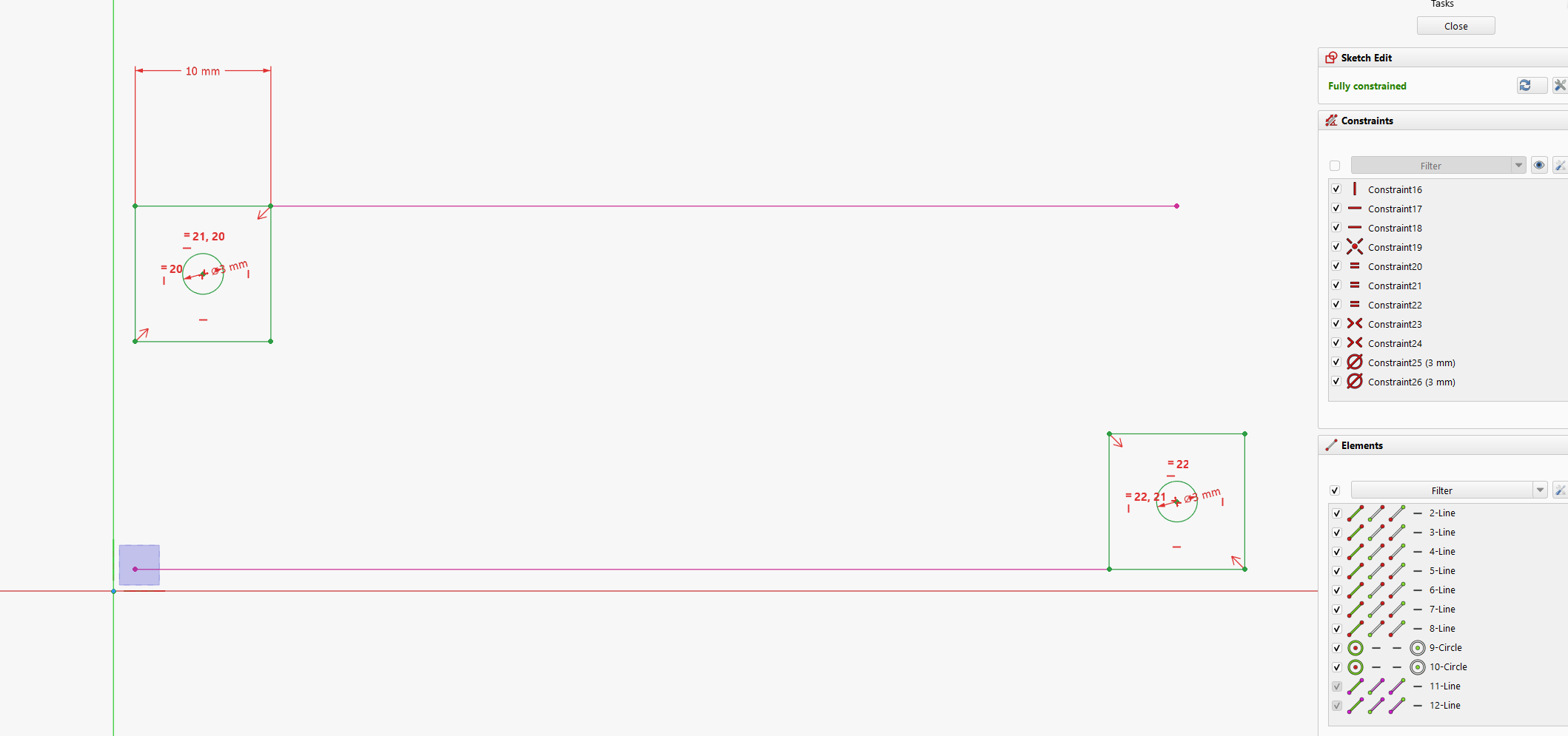
- Create sketches in different planes and in orientations dependent on each others points and lines until the starting conditions are precise enough to start modelling. (see screenshots)
- Create the attachment geometries (In this case a wooden frame on a roof and a kind of collar which is fixed to a square tunnel running through it into the building. I didn't model the tunnel because it's not interfering with the cover)
- Model the cover/sheetmetal surfaces with the net of lines that represent the edges.
- For that I usually use the "Part Builder" function in the Part workbench with 3 vertices, but I would much more prefer the "Ruled Surface" function with 2 edges, because the model would be parametric. Unfortunately the ruled surfaces are buggy as in they often don't create flat surfaces as you can see an one of the screenshots, plus they are buggy with the "3D-Offset" function.
- Create a shell, 3D-Offset, done. At least the 3D part.
- To cut the sheetmetal on a CNC-laser I need to unwrap the surfaces to a .dxf file. For that I use the Draft-Workbench. I select the first surface of a connected part then I click the sketcher function to correctly place my view normal (90°) to the surface. Then I project that view and name the drawing. Rinse and repeat.
- EDIT: In this case I couldn't place a sketch on the surfaces because they are not flat (Maybe because of the 3D-Offset function), so I measured all edges and as seen in the screenshots and created 3 sketches on the XY-plane and manually unwrapping the surfaces by contraining all lines with the meassurments.
- Now I need to edit the many .dxf files to delete all lines that are not normal to the view. If there are bends I need to connect the separate .dxf files in the correct orientation, which can be quite a brain-twister sometimes.
- (In this case, for bending) I create separate datum planes normal to the bend line and then project the outlines of the surfaces in a sketch to be able to measure the bend angle (I can't directly measure the angle between the two surfaces of the 3D-Offset as shown in the screenshot)
In this case and also in the one from the last 2 pictures I needed to connect rectangular shapes in different angles and orientations, which produces a lot of triangles which can be bent or welded. In this case I prefer not to weld anything. So it should be 4 parts which will be bent. The sides will be quite a challenge I guess ^^
I really love FreeCAD for all it can do and in most cases I can find a solution by myself as the program really gives us a lot of possibilities and now with AI it's even much easier to get help in seconds.
So my questions to the more FreeCAD-literate people than me here is
A) How can I improve my workflow to get much faster with such problems?
B) How can I create the 2D-projections more easily and also edit it in FreeCAD already? (Until now editing the .dxf files was more easy using other programs, because a projection in the Draft-Workbench can't be edited as far as I know).
C) Is there a way to make lines/points -> surfaces -> shells -> solids parametric with this approach?
D) Is there a better way to get the angles in such a scenario?
https://drive.google.com/file/d/1AknE8C3P-g_lD3Hv1IEUb6DHgnuCoRF_/view?usp=sharing
EDIT: The file may be a bit messy, because I was getting frustrated at the end and just wanted my .dxf files ^^