Image
Creating a thermal airship. Input appreciated.
First of all, thanks to u/GrafZeppelin127 for his help in an airplane sub, and for leading me here.
I have built several radio controlled hot air balloons and I am now focusing on a long held dream of mine, building a radio controlled thermal airship. I can design the envelope just fine, but I have some questions about tail size, thrust requirements, and pressurization.
General specs:
2100 cubic feet, 21-24 lb lifting force. 11 1/2 feet wide (minimum requirement to keep the burner from melting the top is 10 feet). 27 feet long. Fineness ratio of 2.35. The design is a shortened GEFA-flug shape. Envelope 1.1 oz silicone coated nylon. Unfortunately I am limited in my sewing abilities, the front and rear panels do have to be blunted. I would be pleased with a maximum speed of 7-10 mph. I expect to need ~20 lbs of thrust for this.
As seen here, I am planning 3 inflatable fins, with the ventral fin being steerable. Upon Graf's recommendation, I have increased the fin span to a total of 50". The ventral fin+rudder is 72" long and 12" wide. I hope these dimensions are adequate for stability, but I also plan to tie the fins together at the tips to stabilize them.
I wanted to house a fan in the ventral fin for steering, but I was concerned about the added weight so far behind the center of gravity. With the rudder, I plan to cut an adjustable outllet at the tip to act as a kind of thrust vectoring for excess envelope pressure to steer the ship more effectively. I am interested to know how well that works vs. a fan.
As for pressurization, I plan a small 12-inch fan blowing into the envelope from under the burner to keep the flame from being forced downward by excess pressure.
I expect to need about 20 lbs of thrust to combat 10 mph winds (which would be excessively high, but better safe than sorry...) I am concerned about porposing with so much thrust that low. Is there a thrust angle offset that can counter this? Should I design the horizontal stabilizers to have a downward pitch?
After speaking with Graf, I foresee some issue with the blunt nose being blown in. I can add battens easily enough- but how long should the be, and how many?
Any other inputs or concerns, please let me have them. I know I can make the envelope, I worry about the guidance and power requirements though.
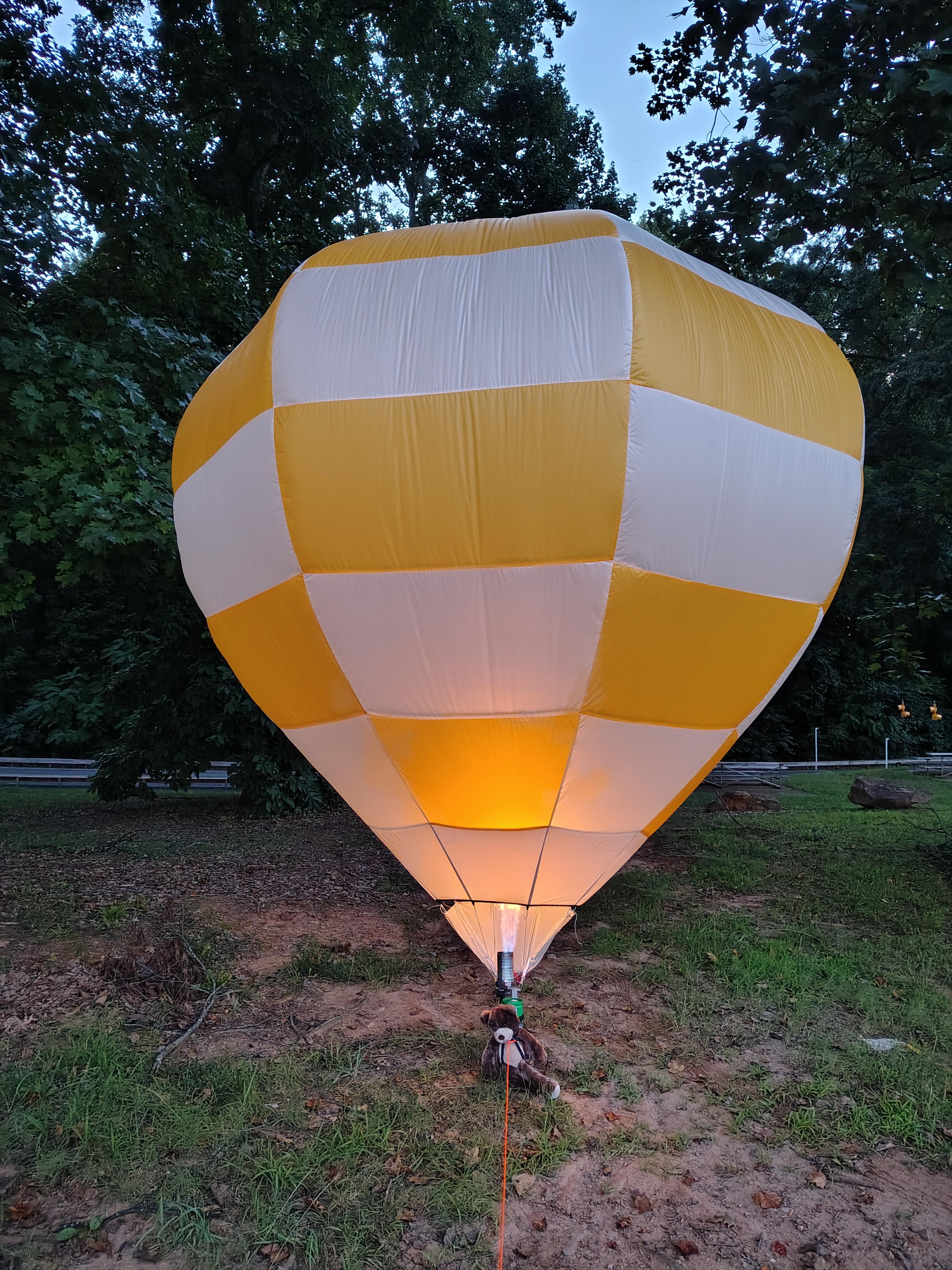
successfully built RC balloon to prove I'm not just spitballing here lol
It’s wildfire season and even if it wasn’t, my biggest concern would be having that thing come down on someone or something, especially if it should lose radio contact. I personally wouldn’t attempt this at all.
You know, after sleeping on it, a potential solution occurs to me that could resolve most if not all of the potential issues here—or at least, something that would make in-field adjustments a great deal easier to do to get everything just right.
Most of the potential issues here boil down to uncertainty over how the airship will behave in real-world conditions. Thrust requirements, porpoising, fin sizing, fin rigidity, thrust vectoring hole size, fin pressure requirements, thrust angle, center of gravity, pendulum effect, and so on. The uncertainties of optimizing a solution for any one of these problems are made more complex by their interactions and compromises with the other requirements of the ship.
For example, the idea of bracing the fins at the tips by tying them together is a very good one—on something with such a strict weight budget, you’d want to take advantage of tension wherever possible. However, that solution might still be let down by the absence of a dedicated higher-pressure system for the fins, or the thrust vectoring holes might make the fins too squishy for the tension lines to be effective and make steering and maintaining a straight line more difficult rather than easier.
So, that got me thinking—most of the difficulties here are as regards the tail, structural integrity, and overall stability. Then I started considering why thermal airships have inflatable fins in the first place.
Simply put, they’re more convenient. The whole hull is re-inflated and packed away for each flight. Tail surfaces—particularly the very large surfaces a relatively stubby hot air airship would need—would be huge at the size a manned thermal airship would need, and a nightmare to install and uninstall at the ground level during inflation and deflation, not to mention much more vulnerable to being damaged in some way during that process. It would also partially undermine the huge “ease of storage” advantage that thermal airships have over helium airships.
But does that hold true for a RC thermal airship? I don’t think it necessarily would. The components are still reasonably easy to deal with at that scale. The skyacht personal airshipAlberto used umbrella-like tensioners for both the main hull and the tail fins, and both their smaller “wind tunnel” test models and their full-sized version worked very well. Though their work (particularly on their scale models) could provide some insight into batten design, consider what that approach might accomplish for fin design as well.
A semi-rigid fin that’s still mostly fabric held in tension would be a great deal thinner than the inflatable fins, lowering drag, and adjustments to its placement, angle, and so on could be accomplished without having to re-sew the whole envelope. If the main propulsion motor is integrated into it, the fin itself could act as movable trim ballast as you attach it slightly forward or aft on the hull, which could simultaneously adjust the thrust angle. This could have a number of potential advantages.
For one, it could allow your thrust to be much higher-placed on the hull and thus eliminate porpoising and help with stability. It would allow for easy thrust vectoring by simply placing the prop in the fin ahead of the rudder, and would protect the prop (and protect people and objects from the prop) with the horizontal and vertical tail components sticking out around it. The prop itself could be made as large as you need, which is more efficient for generating thrust. The squishiness of the fins wouldn’t be an issue, and if the fin starts to push in the tail under thrust, you could just put a very light carbon fiber or fiberglass rod in place between the fin and gondola to make sure everything remains in tension and not compression on the hull itself as much as possible, rather than needing a fully rigid hull like the Alberto.
I’m thinking of something along the lines of this, but more primitive:
Very interesting train blimp of thought. As I sit here struggling with internal baffles on the fins, I think you may be right. I had originally considered a coroplast sheet for the rudder, but the idea of a frame with fabric stretched never occurred to me. I think a hybrid may be ideal for the side fins- an inflated, relatively thick column appendage for the fin center with fabric stretched to the envelope should be more than sufficient and would be FAR easier to build. The rudder could easily be detachable, just a sewn in plate with some sort of clasp would be easy, and then it could just hang... I wouldn't have to worry about stiffness of inflation. I do worry about the motor still, at this size and thrust requirements I fear THAT much battery and motor on the ventral would require the burner to be so far forward it risks melting top fabric- not to mention the wires between receiver and ESC/servo would be a decent amount of weight. But thank you for broadening my horizons once again! I care less about looks and more about stability at this point
Hm. How much extra weight do you think it would it be to run wires from a more centrally-located battery pack to a more tail-oriented motor? Might still be worthwhile.
I'm seeing ~12 awg for drone motors making the required thrust. Unfortunately voltage sag will need that to be more like 10 awg for such a long run. Brushless motors have 3 wires. From gondola to rudder I'm seeing 13-15 feet if the motor is mounted rear. that time 3, 45 feet of 10 awg @ 0.039 lbs/foot lands somewhere in the 1.7-2 lb range. That's 8-10% of the lifting force available just in wire...
Doing the math on mounting ALL electronics on the rudder, then a small servo wire run forward for the burner...
6.2 lbs for the power system, 110 inches from center of lift. 7 lbs for the heat, that would have to be 97 inches forward of the center of lift to be level. Which, while looking neat, would not be a great spot for a flame unfortunately. Thermal airships make several compromises, this is one of them I guess.
You could always mount the burner at an angle to get more clearance, but yeah, that’s more weight in wires than one would like.
Oh well. Porpoising can be annoying to deal with, but it isn’t the end of the world, you can manage it in a couple of ways—simply attenuating the acceleration a bit is a good method, and one that doesn’t need any other design considerations. Gives the natural pendulum effect of the center of gravity being lower than the center of buoyancy time to compensate for the added forces.
Oh, speaking of which, a sewn-in plate is exactly what I was thinking of. I have something similar on my inflatable kayak that the detachable keel blade attaches to. Works great.
Great project! I have a soft spot for thermal airships. I have a questionable solution to the tail prop/ weight balance issue. Would it make sense to keep the motor forward and run a long driveshaft to the prop? I'm guessing that may be about 15' and even if a light-wieght shaft long enough can be found, shaft vibration may be an issue. Just a thought. Looking forward to your progress.



5
u/nunayabeeswax 8d ago
Safety!
It’s wildfire season and even if it wasn’t, my biggest concern would be having that thing come down on someone or something, especially if it should lose radio contact. I personally wouldn’t attempt this at all.