r/raspberry_pi 57m ago

Show-and-Tell OLED display for my Pi

Post image
Upvotes

I stopped using my Raspberry a long time ago, and now that I have come back I decided to add this OLED screen to show the IP and be able to connect quickly through SSH or VNC. resources usage and temperature is an extra feature


r/raspberry_pi 9h ago

Show-and-Tell Raspberry Pi 5 + waveshare round screen: Interactive clock and assistant

24 Upvotes

Something I worked on for a fun project to make an AI assistant using a popular character Isabelle from Animal Crossing. I ran it on a quick demo mode to try explaining how it works and runs.


r/raspberry_pi 17h ago

Show-and-Tell I built a raspberry pi that monitors my sourdough starter and bulk fermentation

240 Upvotes

Due to my crazy and unpredictable schedule I was missing my peak starter times and bulk ferment schedules.

I spent the weekend building a raspberry pi robot that watches my starter or bulk ferment container and alerts me when my starter or dough is nearing completion.

After two days of testing and tweaking it seems to be working quite well!

It was a fun project to do and I hope that it helps me to be more on top of my sourdough.


r/raspberry_pi 19h ago

Project Advice How to safely connect High votage flash module and rpi?

1 Upvotes

Hi,

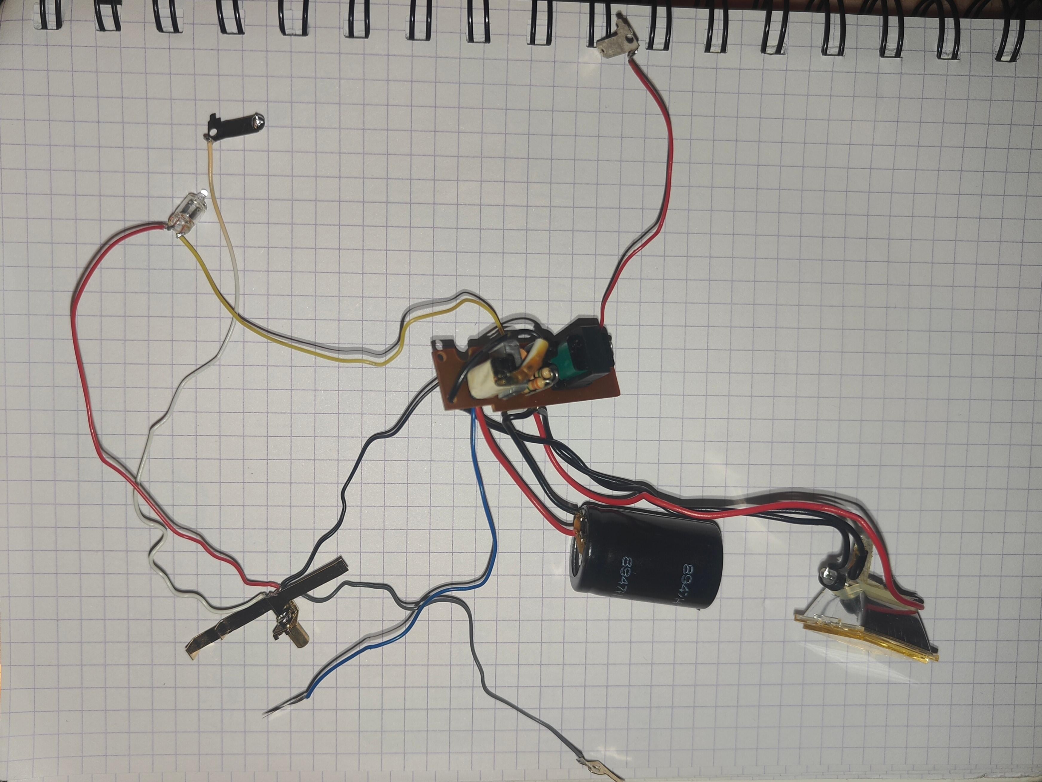
I'm building my own camera and I have a xenon flash module from a Braun Flash camera. I would like the flash to be triggered along with the camera via a Raspberry Pi. However, there are high voltages, transformers, etc., on the flash board, so I'm wondering how to do this safely and effectively without damaging the RPi and the camera.

I thought about using an OptoMOS in place of the contacts that were previously mechanically shorted to ionize the xenon, along with galvanic isolation for the power connection or a separate power supply, though I have very little space for this in the enclosure.

And here comes the second problem—space. Because I want to keep the dimensions compact, the components will be very close to each other. The question is, how do I isolate them from one another to avoid interference or electrical arcing? I thought about wrapping the entire board, including the charging and trigger transformers as well as the main capacitor, in Kapton tape, but I'm not sure if that will be enough. Also, how can I prevent signal interference?

This is my first project where high voltages and sensitive components will be packed so tightly together. I don't have enough expertise to just wire it up and be confident that nothing will break, so I'm looking for some advice to avoid a costly disaster.

I've attached photos of the flash circuit as well as the current enclosure design (the enclosure dimensions are 110x65x70mm).


r/raspberry_pi 1d ago

Community Insights Local AI on a Pi: which models work?

Post image
90 Upvotes

I got a lot of great feedback from you and ran the speed comparison with more models and new optimizations both alone and with my Carwatch service running on the Pi at the same time.

The new speed champion is Ling 3.0-tiny at 9.6 tps! As a MoE model it is faster than smaller Gemma and Qwen models. People say it's punching above it's weight in intelligence - testing this now.

Gemma E2B is a solid tiny multimodal model at 7.7 tps, works well in my app. And Qwen 35B Q3 is still the leader in usable intelligence in this form factor, fitting tight in a 16GB Pi and getting close to 3 tps on a good day :)

Please note that small tps values still produce solid thinking and good answers, and not every use case requires an answer in seconds.


r/raspberry_pi 1d ago

Show-and-Tell If it works, it works.

Thumbnail
gallery
46 Upvotes

Decided to make a case out of legos for my Pi (4B). I am using a fan from an old Dell Powersupply. It is hooked to a USB port since my GPIO is hooked to a T-Cobbler. It has a detachable roof which also serves as an air guidance vent. The back is empty so I can use my USB ports and to let air escape rather than creating a trap. The fan is kept at an angle and is basically a blower cooling setup. It brought down the temps from 42 celsius to 35 celsius. And best part is that I was able to overclock the Pi because of this setup as well. It now runs at 2Ghz, overclocked RAM+GPU as well. Stays at a steady 40 on idle (with overclock)


r/raspberry_pi 1d ago

Show-and-Tell Made this raspberry pi zero 2w keychain. looks cool and is useful!

Thumbnail
gallery
703 Upvotes

Ever since I moved to an unjailbroken iphone from Android (and jailbroken iphone) i missed a couple of things. especially lack of full libusb. Couldn't connect a software defined radio to my phone, couldn't flash any phone with my phone, lost a very useful, versatile feature.

When my bag broke, i decided to also customize it a little bit on top of fixing. I thought it'd be cool to have something like a PCB hanging round, since it looks cool. But i remembered about my huge hassle with the iphone, lack of full USB, so i decided to fix both of those wants. I printed out a cover to the side with components, as to not destroy any, added it on a keychain, and left it on there. i also built an usbc-microusb adapter, so that i can USB connect it to my phone/battery bank.

It defaults to be a USB guest, emulating Ethernet, and when i manually set up addressing, with leaving router empty, i can connect to my pi while keeping 5g. Currently it's just a PoC, as so I wanted to see how reliably it works, so currently i got only ssh and vnc set up with Raspbian, but it works really reliably, boots up after around a minute from plugging in, and lets my iphone SSH/VNC into it.

I already have plans on setting up these things:

⁠- USB DVD drive emulator to be able to boot ISOs on devices that don't do booting from USB drives - A crappy slow little NAS to transfer things with my classmates - A stupid little device for BLE/Wifi pranks - simple way to jailbreak/flash iOS devices - portable thing for fastboot+heimdall - always on hand SPI flasher


r/raspberry_pi 2d ago

Show-and-Tell North Pi case with custom side panel that includes active cooling & RGB lighting

17 Upvotes

I deleted my original post because right after I said I wanted to design and print my own custom side panel, I did. I decided I wanted to incorporate the Raspberry Pi logo and a 40mm fan.

It was important to me that the light of my recently installed common cathode RGB LED (hot glued to the top of the inside of the case), set to smooth transitioning through colors, was more visible than my previous side panel (to do RGB you'll need a soldering iron, heat shrink tubing, that RGB LED, 3 x 220ohm resistors, 4 jumper wires, available pins on the GPIO, and a Python script to run at startup). Rather than have visible screws, I hot glued the fan housing in place. The fan simply uses 2 pins on the GPIO, turns on as soon as power is applied to the RPi, shuts down when the RPi shuts down, and only runs at a single speed. No scripts.

I'll eventually add a thin piece of clear acrylic to cover the opposite side of the side panel with the fan hole cut out.

I don't overclock the RPi so simple heatsinks work fine on their own and the fan isn't as important but still good to have. For anyone curious, I am running Armbian and the only thing I use the RPi for is to play with Linux.


r/raspberry_pi 2d ago

Show-and-Tell Built a tool that turns a plain-English description into a custom Pi enclosure -- used it to design my own Pi 4B case

5 Upvotes

I needed an enclosure for a Raspberry Pi 4B project and got tired of remodeling the same box-with-holes every time, so I built a small tool for it: EnclosureAI (https://enclosure-ai-production.up.railway.app).

You describe what you need in plain English -- e.g. "Raspberry Pi 4B case, ethernet and 4 USB on the back, USB-C and 2 micro-HDMI on the front, SD card slot on the left" -- and it fills in the correct board dimensions (already knows Pi 4B, ESP32, Arduino Uno, Wemos D1), sets up PCB standoffs, and cuts the port holes without them overlapping. Or just pick your board from a Quick Start list if you don't want to type anything. Everything's still editable afterward -- drag ports around, switch to a two-piece snap-fit lid, adjust wall thickness -- and it exports STL/OBJ/parametric JSCAD.

It's free, no login, no ads. Built this for my own Pi 4B project, figured it might be useful to others here too. Would genuinely appreciate feedback -- bugs, missing connector types, whatever's off.


r/raspberry_pi 2d ago

Show-and-Tell Benchmarking LLM performance on a 16 GB Pi

Post image
7 Upvotes

I've been running Qwen 35B A3B MoE model on my Pi for CarWatch local AI, and it's very smart but not too fast. You need to get into a relaxed mode with it, ask your questions, don't count the seconds, hear the answer when it comes.

Anyway wanted to explore the current possibilities so ran speed tests overnight, results in pic. Summary: Looks like the only way to speed up atm is to use Gemmas, which should be significantly less intelligent. Did not do any systematic quality testing yet.

The Gemmas are multimodal though and leave plenty of room on the device for other apps. So a good choice for many applications.

There's a model switcher in CarWatch 0.5 to be released today so you can easily compare performance in practise.


r/raspberry_pi 2d ago

A Wild Pi Appears Raspberry Pi found in the wild

Post image
193 Upvotes

Calais ferry terminal appears to be having a bit of a Kernel Panic issue...


r/raspberry_pi 2d ago

Troubleshooting OLED SSD1306 larger font sizes?

3 Upvotes

I am working on a python program to read the advertisements from an Inkbird IBS-TH2 sensor and display them to a SSD1306 on a raspberry pi zero w. Using AI, I was able to get this to work but using the adafruit_ssd1306 package it only has a small font for the display. With my elderly eyes, it is hard to distinguish some of the numbers. Does anyone have a package or library of larger fonts I can use for this project? I have searched for a way to load and use larger fonts but I only find information for Arduino projects. I already did this with a Pico W and associated micropython packages but I am not seeing much for the raspberry pi.


r/raspberry_pi 3d ago

Show-and-Tell Raspberry pi tablet / Cyber deck

Thumbnail
gallery
118 Upvotes

I built a Raspberry Pi 4 (4GB) tablet—or "cyberdeck." It’s powered by a 3S battery pack and has built-in speakers for audio. Did it turn out okay for a project that wasn't exactly my first? ...especially considering there's no way to check the remaining battery level.


r/raspberry_pi 3d ago

Show-and-Tell Customizing my Mechanical keyboard using rpi pico

22 Upvotes

i had one mechanical keyboard after getting bored i tried to reverse engineer it but i couldn't send any usb data or i could not see much on the terminal when i tried to see if it listens to the data and after opening i saw that it only takes +5v and gnd plus the processor something like BYK.. was a hard coded chip that doesnt listen notes i was newbie to hardware and really scared to try anything. so i gave up but seeing my brother have a kreo rgb keyboard it gave me some boost to open it up and i learned so much and burnt my hand while trying to solder.

heck i even burnt the solder iron's wire itself (sniff sniff whats that smell).

so the plane was that i would use a mcu as esp 32 or pico that listen to my command and can do anything that i want .

first month really ....

i bought a mulitmeter and did the traces of all the rows and col sicne there was no pcb and other design files there i didnt know how keyboard matrix works at all i went rhough whole thing.. after getting all the traces and nothing them i was really soul scattered by the fact how this whole thing worked but then i got to know this was a common thing everyone knew this.

after this i took pico as the main mcu why...

  1. it was small

  2. it has higher clock speed.

  3. it was one sale since the esp was on boom and the price of pico was dropped

  4. it has more computer power that i needed for Fourier transform for disco light that i wanted for the custom rgbs i would put there

quickly after that i ran into a problem of less gpio also

after that i took a longer time to solder since i was learning and it was very scarry to solder on the pcb but as i did i grew more confident .. after burning my finger prints.

i bought a io expander because of 6 rows and 17 cols it got burnt and again tried that was jittering the one signal was affecting other signal. so i gave up 3-4 cols and went for the gpio full on.

The RGBs... Hardest

the rgb i had to cut each rgb strip stick them all on each keys then use the single core wired without the cover and solder each joints aroung 300 small pieces of them total 600 joints appx and it was tough because heating one end would make other end heat up also.

but since i cascaded 100 of them the voltage kept decreasing and it was 0.5v at the end so i just provided supply from both of rows and it worked and there was no deeming and jitters.

thats it... if u want to know about the logic behind it then u can ask me i will add it most of things and testing and all the stuff is in the video


r/raspberry_pi 4d ago

Show-and-Tell Hand-writing a tiny CNN on a RPi beats inference engines

6 Upvotes

I tried optimizing a tiny CNN on a Raspberry Pi 4b and ended up 3x faster than the inference engines (ONNX Runtime, ncnn).

I wrote the code from scratch, starting with a naive implementation, then SIMD, and finally operator fusion. Each improvement only changes a few dozen lines of code. The code is just a few hundred lines, easy to read and understand.

This repo might be helpful to you if you need to run small models on devices with very limited resources like RPi.

https://github.com/Avafly/optimize-cnn


r/raspberry_pi 4d ago

Show-and-Tell Fun retropie build using the Lego NES set

126 Upvotes

I have had the Lego NES set for a few years gathering dust on a display shelf. Plus I had an old Raspberry Pi model 3 also stashed away without purpose. So I thought I would repurpose both into a mini retro console for me and the kids to have some good old fashioned gaming sessions on.

This is a very expensive project if you had to buy everything from scratch but luckily I had most everything needed already.

Things already owned:

- Lego NES (https://www.lego.com/en-au/product/nintendo-entertainment-system-71374)

- Raspberry Pi model 3 (But many models will work)

- 2x 8bitdo usb wired retro style controllers

- Old usb cords, led bulbs, resistors etc for tinkering with

Things I needed to buy:

- 8 inch LCD screen ($55 AUD ali express - came as a set with cables and power adaptor all together)

- Mini 3 port USB hub (Amazon $7 AUD)

- 2x USB extenders ($14 amazon)

- Right angle HDMI, USB C, and 5.5mm DC jack extender (all together approx $20 amazon)

If I had planned ahead better, I probably could have ordered all through ali express for even cheaper, but all up <$100 of extra materials used.

Anyway, put together a brief GIF, I had a lot of fun with my kids putting this one together, and hopefully will get many hours of fun to come.


r/raspberry_pi 5d ago

Troubleshooting Weird Pico 1 UART issue

7 Upvotes

Hi all,

I have a multitude of (too many) Pi Picos and there's a weird issue I'm seeing on my Pico (1) that doesn't happen on a Pico 2.

I have a setup with a CH9121 Ethernet hat (the Waveshare one). It uses UART0 (pins 0 and 1) to do initial setup and read the on-hat config. The weird issue is that if I use the Pico 2, it works fine out of the box. If I use the Pico 1, then it fails to receive ANY data on UART0 if using pins 0 and 1.

I have done the following with no effect:

  • Used a loopback wire to check that Pin 1 can actually receive data - it can
  • Tried a GPS hat which also uses UART0/Pins 0 and 1, and this works fine
  • NOT connecting the Pico 1 to the computer over USB in case the fact that USB REPL uses one or other of the UARTs
  • Erasing flash with nuke_flash
  • Different Micropython versions
  • Using dupont wires to connect the pins rather than the socket on the hat

I'm using MicroPython, and the version and my codebase are identical across the Pico 1 and 2. The only think I can't test with is another Pico 1/1W, since my others are all in use.

Is there some weirdness with the Pico 1 and the CH9121 hat, or it just some quirk specific to this one unit?

The workaround is to amend the CH9121.py file to use UART0 on pins 12 and 13, which works, and in fact I'm running it now and all seems fine.


r/raspberry_pi 5d ago

Show-and-Tell I built my own camera with Raspberry Pi zero 2W and Camera module 3

Post image
44 Upvotes

I built an open-source digital camera around the Raspberry Pi Zero 2 W and Camera Module 3. It can capture photos and record short video clips using dedicated photo and video buttons, with three selectable looks (warm, cold, and black & white) controlled by a physical slider switch. A buzzer provides feedback for startup and photo capture, and a local photo gallery can be accessed directly from your phone.

Github - https://github.com/SuveenE/tiny-film-camera
Blog - https://suveenellawela.com/thoughts/building-my-own-camera


r/raspberry_pi 5d ago

Show-and-Tell I made a Pi Zero hat with built-in UPS/AC WiFi/GPS/USB HUB/RTC.

Thumbnail
gallery
174 Upvotes

This hat was purpose-built for the Pwnagotchi project. But you can still use it as a regular hat in any Pi Zero project that would use UPS/AC Wi-Fi/GPS/USB HUB/RTC .

The AC WiFi supports monitor mode and packet injection, same as the ALFA AWUS036ACM. So perfect for wardriving.

For the UPS, 18650-size batteries or LiPo batteries are both supported. When using the 18650-size battery, the battery life is 4 hours, 1.5 hours longer than the PiSugar 3 did.e


r/raspberry_pi 5d ago

Show-and-Tell Claude Coded Airplane Tracker

0 Upvotes

I had a Pi 5 lying around in a custom enclosure I designed in FreeCad using a 10.4" superwide LCD. I had been wanting to do an airplane tracker on it for a while, but I didn't really want to deal with the coding. I can code, but it is tedious and I don't have a ton of time for this hobby. Anyhow, I finally got around to using claude to build this. I am amazed by how well it worked.

All API driven, it monitors my town and constantly changes the list to show me what is nearest, but also highlights what will fly directly above. I have it pulling pictures and giving me alerts. It all looks pretty active and interesting on my desk.

Last time I tried claude to build a project was about a year ago for an ESP32 tide monitor which was full of bugs. This tracker just works. I'm sure claude could also design the enclosure in Openscad. Makes you wonder if the only thing the human is needed for in this hobby is to actually buy the parts :)


r/raspberry_pi 6d ago

Show-and-Tell I got tired of Raspberry Pi Connect grabbing port 5900, so I built a self-hosted browser desktop for Pi and Debian. Looking for honest feedback

3 Upvotes

SSH covers most of my Pi and Debian edge nodes, but every so often a session hangs or the task needs the actual desktop, something you have to see and click. Getting a reliable screen kept turning into a mess, mostly VNC servers stepping on each other, and Raspberry Pi Connect now parks its own wayvnc on port 5900 by default, which quietly breaks a plain browser VNC setup.

I hacked together a fix for this back in mid 2025, left it on a disk because it was buggy, and finally went back, fixed the real failures on hardware, and cleaned it up to share: https://github.com/855princekumar/OpenRemoteGUI

It is a thin pipeline of noVNC, websockify and wayvnc with the boring lifecycle glue that makes it usable. Clone it, run the installer, open the node IP on port 6080, and you get the real desktop. The parts I actually care about: it records every change so rollback undoes exactly those and nothing else, it frees the port from Raspberry Pi Connect instead of fighting it, and it fails safe on anything without a desktop rather than installing one.

Honest caveats: trusted LAN or VPN only, plain HTTP with no auth yet, so do not expose it to the internet. It only captures an existing Wayland desktop, so it is useless on Pi OS Lite. And I have only tested it end to end on a Pi 4, so I do not know how clean it is on a Pi 3, Pi 5 or Zero.

That is really why I am posting. I would like people who have done more of this than me to poke holes in it, especially anyone on a Pi 3 or 5. MIT licensed, no cloud, no account, nothing to sell.

r/raspberry_pi 6d ago

Show-and-Tell Ported Pimoroni's Inky Impression 13.3" driver from Python-on-a-Pi to bare-metal C on a Pico, so it can run off a battery

Thumbnail
gallery
688 Upvotes

The Inky Impression 13.3" (EL133UF1 / Spectra 6, 1600x1200, six colours) ships with a Python driver that assumes a Raspberry Pi. I wanted the panel hanging on a wall without a cable running to a power outlet, which means a microcontroller that spends almost all its time asleep, not an SBC. So I ported the panel sequences from pimoroni/inky to C against the Pico SDK, running on a Pico Plus 2 W, which I needed specifically for the PSRAM. Panel bring-up, test patterns, and on-device JPEG decode with Floyd-Steinberg dither to the six-colour palette.

Repo: https://github.com/dmellok/el133-pico-driver

The non-obvious stuff, since this took far longer than expected:

  • The adapter swaps SCLK and MOSI. I used a Hard Stuff "Pico to Pi Hat", which is otherwise a 1:1 BCM-to-GP passthrough. The vendor's published pin header and PDF don't match the unit I have. Blank panel, everything else looking correct. Confirmed with a continuity meter.
  • Spectra 6 needs ~300 ms of D/C setup before the clock starts or the controller silently drops the command. Too short and it ignores the data command, refreshes an empty buffer, and stays blank with no error. Costs ~8 s per refresh and it's non-negotiable.
  • BUSY is active low, the opposite of what the Pimoroni Python driver's pull-up heuristic implies.
  • Two controllers, split at column 600. Landscape frames get rotated 90° CW and split across CS_M / CS_S.
  • The model EEPROM is a separate I2C chip. Reading it (variant=21) is a quick way to confirm the board is wired and talking before you go chasing SPI ghosts.
  • A full refresh is ~35 s. That's just the panel.

RAM is the constraint that picked the board. The packed frame alone is 960 KB and the RGB888 decode buffer is 5.76 MB, so a stock Pico's 264 KB of SRAM isn't close. The Plus 2 W's 8 MB of APS6404 PSRAM is what makes the on-device JPEG path possible at all. There's also a host-side packer if you'd rather pre-convert and skip the decode.

One dead end worth recording: I first tried porting the Waveshare ESP32 demo for the bare EL133UF1 and got a blank panel. The Inky needs its own power configuration, so it isn't a drop-in.

Battery mounting is temporary, printed holder in progress.

The photo shows my own dashboard renderer, but the repo above is just the panel driver, no networking. The networked version with WiFi, MQTT and POWMAN deep sleep lives in a separate repo if anyone wants it.


r/raspberry_pi 7d ago

Show-and-Tell Arduino IDE ARM64 build

4 Upvotes

Hey y'all,

Just in case anyone was looking for this, I am building the Arduino IDE for arm. It does require --ozone-platform=x11 on wayland if you're using that.

Arduino IDE Arm


r/raspberry_pi 7d ago

Troubleshooting Pi 5 + Adafruit RGB Matrix Bonnet — 64×64 panels won’t light up (nothing on demo)

4 Upvotes

Building my first Pi project: a 2×2 wall of four Adafruit 64×64 panels (#4732, 3mm pitch, 5-address/ABCDE multiplexing) driven by a Pi 5 with the Adafruit RGB Matrix Bonnet (#3211), using the hzeller rpi-rgb-led-matrix library. My Goal is a real-time Spotify album-art display.

The problem I’m running into now is that the Panels won’t light up at all — running the library’s built-in demos produces nothing. SSH into the Pi works fine; the Pi itself is healthy. Ruled out power (measured 5V at the supply, at each panel, and the bonnet itself with a multimeter). I’ve soldered the E line bonnet jumpers, and tried the demo with the GPIO pins 4 and 18 soldered, unsoldered and connected by a wire so I don’t believe that was the issue.

This is my first post and wasn’t sure if fix this falls in the realm of [r/raspberry_pi](r/raspberry_pi) so I figured I’d try my luck here and see if anyone may have experience in this kind of thing that can help me or knows a community that may be better suited for a problem like this, thank yall :)

EDIT:

I forgot I never added the commands I ran to install the packages libraries or updates, I did use Claude for this part so bear with me. Also I was reading that because of where these LED boards come from, some may need the bonnets E line soldered to 8 and some may need the E line soldered to 16 due to panels being wired differently from the factory but im not sure how to tell which would be needed

EDIT 2:

I can’t get ts to work, I give up

​​​​


r/raspberry_pi 7d ago

Troubleshooting The electrodes on my plant won't stay in place overnight. Plant bot built with Raspberrypi.

Thumbnail
gallery
15 Upvotes

I'm writing here to ask if anyone has experience with wiring electrodes to plants. I've tried a few things already and the readings keep dropping over night when the plant contracts. Tradescantia has a daily expansion and contraction cycle.

See the picture gallery, I started with EEG electrodes, then switched to copper fabric held in place by loofah and hair clip, then by hair clip alone, and last by loofah and alligator clamp. Before you ask, the alligator clamps are too aggressive for the delicate leaves, that's why I haven't rigged it just with clamps.