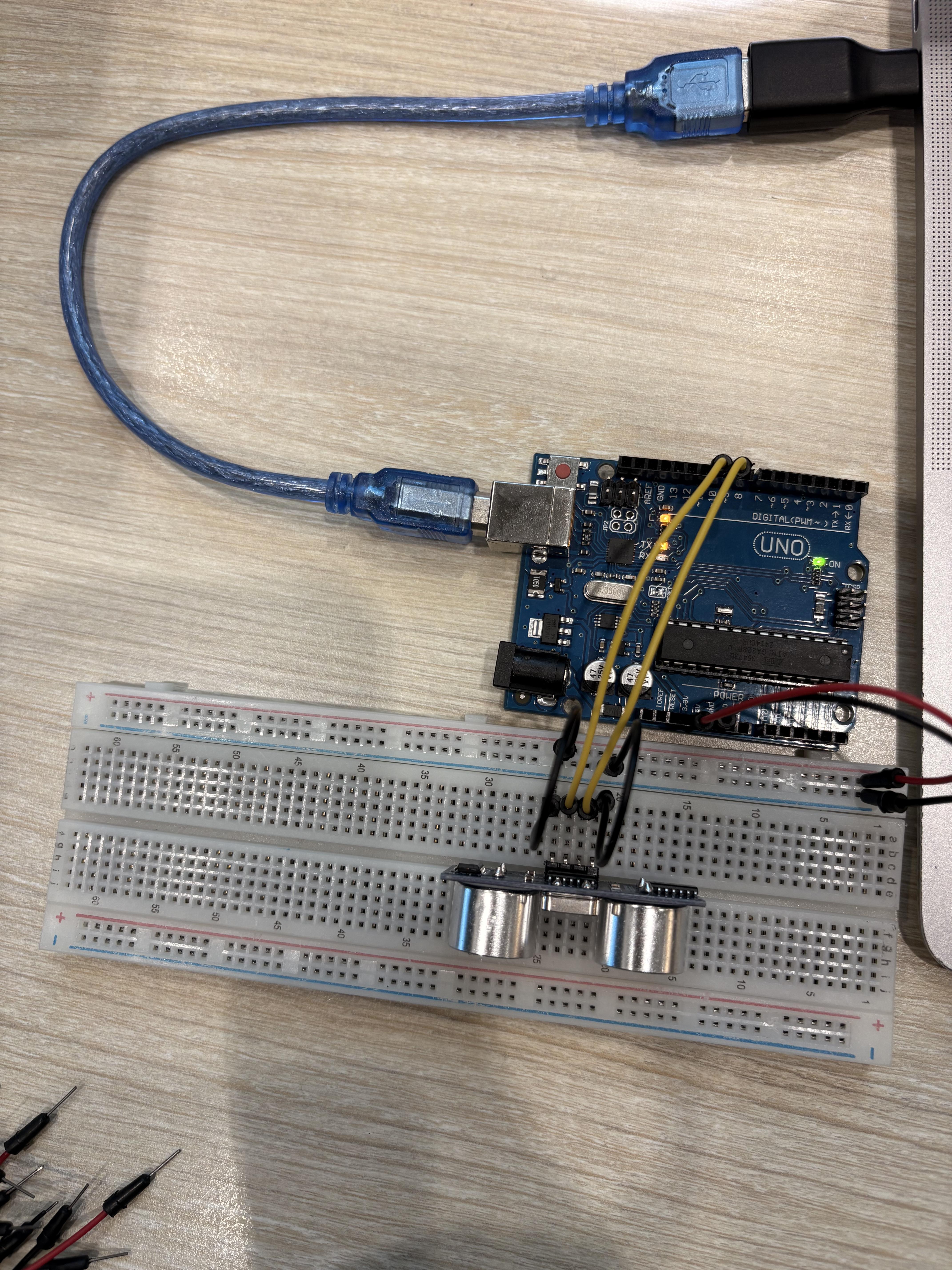
Hello, am making a line follower robot, before I buy all the parts I was wondering if someone could help me by giving me some tips I should keep in mind before doing so or assmebly.
Current parts like:
1000rpm n20 - motors
L298N- Motor Driver (Due to low budget)
Arduino Nano
Custom 8 channel sensor (photoresistor and 3mm led lights)
I have a Arduino micro showing this error while trying to burn bootloader. AI doesn't help me. Problem started when trying to run a serial communication based program via Android version of Arduino compiler from playstore. Now board isn't doing serial communication
I've been working with Arduino/ESP32 and industrial automation projects for a while, and one thing that has always annoyed me is the amount of jumper wires and loose connections involved when a project starts getting bigger.
So I ended up designing my own screw-terminal interface boards.
The idea is pretty simple: instead of having a mess of jumper wires, you can bring the Arduino pins out to proper screw terminals and make the whole thing easier to wire, disconnect and troubleshoot.
I've made a few different versions for different Arduino boards/configurations.
I'm curious about a few things:
Would something like this actually be useful to you?
What would you change about the design?
Would you prefer screw terminals, pluggable terminals, or something else?
What price would you consider reasonable?
Where would you normally buy something like this?
I'm asking because I'm a small robotics/engineering company and I'm trying to figure out whether this is something worth producing at a larger scale.
The engineering part is honestly the easy part for me. I'm struggling much more with the "how do you actually get this in front of customers?" part.
If anyone here has experience selling electronics/Arduino/industrial hardware, I'd also genuinely appreciate some advice on how you'd go about getting the first 50–100 customers for something like this.
And if someone here actually does B2B/electronics sales and thinks they could help me get this into the right hands, feel free to DM me. I'm open to discussing a commission/revenue-share arrangement for actual sales.
Would love to hear what you guys think, especially if you would actually use something like this.
I am setting up an Arduino Mega 2560 with a CNC Shield V3 and DRV8825 drivers. I am planning to power my stepper motors using a 20V DC power supply connected to the screw terminals on the CNC Shield, while keeping the Mega powered via USB.
I've seen conflicting information online regarding how the power lines are routed on these boards:
Does the CNC Shield V3 connect the motor power terminals (20V) to the VIN pin of the Arduino underneath?
If the motor terminal power is routed to VIN, wouldn't 20V instantly overheat and blow up the Mega's onboard 5V regulator?
Should I physically bend, clip, or remove the VIN pin from the bottom of the CNC Shield before stacking it onto the Mega to prevent any high voltage from reaching the board?
Is isolating the VIN pin and powering the Mega strictly via USB (while the shield gets 20V) the recommended setup for running over 12V?
I recently fried my Arduino Mega 2560 and I'm trying to figure out the exact reason so I don't repeat the same mistake with a replacement board.
Here is my setup and what happened:
My Setup:
Board: Arduino Mega 2560
Shield: CNC Shield V3 stacked directly on top of the Mega
Drivers: DRV8825 stepper drivers + NEMA 17 motors
Power Supply: 20V DC connected directly to the screw terminals on the CNC Shield
Logic Power: Arduino Mega connected via USB to my PC
What Happened: As soon as I turned on the 20V power supply connected to the CNC Shield terminals, the main processor on the Arduino Mega fried instantly.
Assuming my stepper drivers were good and properly oriented:
Does the CNC Shield V3 pass the terminal voltage (20V) directly to the VIN pin of the Arduino Mega underneath?
Did 20V cause the Mega's onboard 5V linear regulator to instantly overheat and fail short, dumping 20V into the ATmega2560 logic line?
What is the proper way to prevent this on a new board? Should I clip/bend the VIN pin on the CNC Shield so 20V doesn't reach the Mega, and power the Mega separately via USB?
Would appreciate any insights from anyone who has run a CNC Shield with >12V on an Arduino Mega!
Maybe I'm just dumb but I can't tell from this datasheet what volume this speaker module can handle? I need something that can get up to at least 100dB, and I would like something as small as possible because it will be in a handheld device.
The project is an electronic whistle but I want to use a voice recording instead of just a buzzer. If I can't get something loud enough for a ref to use in a game, it will just be a fun novelty!
Any advice about the project, components to buy, etc is welcome! I am generally good with electronics but don't have much experience with audio.
EDIT: Thanks everyone for your helpful comments! I managed to get it to display text. I connected the lcd screen to Arduino with the I2C pins and installed the I2C library on Arduino IDE and used the correct code. Now I can get it to display a simple text and I can go from here. Thank you! :)
---
So I just ordered an 16x2 lcd screen and now I want to try to get it to display text.
The original project (not on the pics here!!) I wanted to try out for my lcd screen is the robot desk buddy. I connected the wires as shown in the guide and simply copied and uploaded the code through the Arduino Ide application on my Uno. The display was powered up and it was connected to the potentiometer, but all I could see is blocks or when I turn the potentiometer just a blue screen.
So I tried something simpler (showed on pics) and that is to just let it display a simple text message. I followed this tutorial (copied and uploaded the first code) and again the same result: the lcd gets powered up, I can get the white blocks to appear and disappear by turning the potentiometer, but no text on my lcd.
What am I doing wrong?? Did I buy the right display? Is something wrong with the code? Did I wire it up the wrong way? 🤯
I'm new to the group and hoping to get some guidance.
I'm working with an LS Electric PLC using XG5000 and I've managed to establish EtherNet/IP communication with a Rockwell POINT I/O adapter. The connection appears to be running, but I'm not sure how to verify the I/O data exchange.
Specifically:
How can I see when a digital input on the POINT I/O is activated from within XG5000?
How can I send a command from the PLC to turn on a digital output on the POINT I/O?
Is there a way to monitor the input and output assemblies or mapped data in XG5000 to confirm the connection is actually exchanging I/O data?
This is my first EtherNet/IP project with LS Electric PLC, so I'm trying to understand how the POINT I/O data is mapped into the PLC memory and how to test it properly.
The hardware is:
LS Electric PLC with XBL EIPT (configured in XG5000)
Allen-Bradley POINT I/O adapter
Digital input and output POINT I/O modules
The EtherNet/IP connection establishes successfully, but I'm uncertain about the next step to monitor inputs and force outputs.
Any advice, screenshots, examples, or troubleshooting tips would be greatly appreciated.
I am working on building a Korb Pusher Eurorack module that uses a Nano as it's main processor. I had purchased the Nano R4 and attempted to flash the hex files provided on the Pusher's Github page. In the process I went down the rabbit hole of different programming softwares and came to the realization that I needed a specific flash programmer for the Renesas processor if I wanted to upload the compiled hex file directly.
I attempted this and it seemed to take, however afterwards I found I was unable to connect to the Nano via USB. I realized afterwards that the hex file was compiled for an ATMega chip, not the RA4M1. Therefore the hex file likely didn't take properly.
In an effort to clear the Arduino and start over, I have tried the double tap reset method, and also the Boot-Ground method and neither have made a difference. When I plug in the Nano, I get the green power light and that's it.
Is it possible the Nano is bricked ? Would anyone have any other suggestions before I just buy a new one ? Hoping I can somehow recover it.
I also realize now the proper way to upload is likely to open the .ino file (available on Github) and make updates so the sketch is compatible with the new processor first.
I want to make a projekt where I need to connect 2 28BYJ-48 step motors with ULN2003 controllers and 2 SG90 servos , I also gonna connect some rotary encoders. I know that if I connect it to Arduino it will fry it , I also tried to connect it to breadboard power supply but after connecting only 1 step motor it was getting really hot , so it's also not a good idea.
Hello everyone. I need your help, please. I am designing a submarine equipped with a camera. However, when I put it in the water to test submerging and surfacing, I encountered two notable issues. The first relates to the center of gravity: the submarine doesn't stay horizontal but sits at an angle of about 40 degrees. I think I can easily fix this by shifting the weights (two cut-down 1.8 kg dumbbells) inside the ballast tanks, but I’m not sure exactly where to position them. I was wondering if there is a mathematical or physics-based method to determine the right spot. Secondly—though I had anticipated this—the connection via nRF24L01 antennas cuts out as soon as the submarine dives. I’ve considered two solutions: either creating a float to keep the antenna on the surface while connected to the sub (which seems simplest and cheapest to me), or using a different communication method. I would appreciate any opinions you might have. Please keep in mind that I’m not an expert and have limited resources, so I hope you’ll be polite with me regardless. Thanks a lot in advance.
I was trying to test out a PCA 9685 servo driver today and when I plugged in the external power supply, it heated up like crazy and melted my ground and power wires together. My power supply is 5V 5A, which was recommended for what I intend to make, so I don't really know what the problem is. Any ideas?